特性
- Dual output 3+1 or 2+2, or single output 4-phase
- 2.7V to 5.5V supply voltage
- 5A per phase output current capability
- Small solution size
- High efficiency (94% peak for 3.3V VIN, 1.8V VOUT, L = 220nH)
- Low IQ in low power mode
- Proprietary control scheme reduces the output capacitor and supports fast load transients (such as 50A/µs per phase)
- Voltage, current, and temperature telemetry through integrated ADC plus auxiliary inputs
- ±0.7% system accuracy, remote voltage sensing
- I2C and SPI programmable output from 0.3V to 2.0V
- Independent Dynamic Voltage Scaling (DVS) for each output
- Soft-start and fault detection (UV, OV, OC, OT), short-circuit protection
- 4.7mm x 6.3mm 35 ball TFBGA with 0.8mm pin pitch
描述
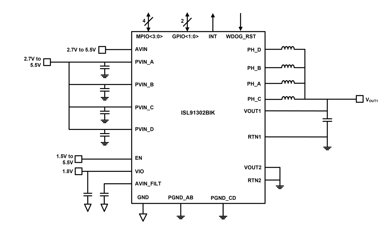
The ISL91302BIK is a highly efficient, dual or single output, synchronous multiphase buck switching regulator that can deliver up to 5A per phase maximum output current. The ISL91302BIK features four integrated power stages and two controllers. The ISL91302BIK can assign its power stages and controllers to two dual-phase outputs (2+2) or one three-phase and one-phase output (3+1) or one-phase output (4+0). This flexibility allows seamless design-in for a wide range of applications in which dual, triple, or quad-phase outputs are needed, such as CPU and GPU core power mobile applications.
ISL91302BIK integrates low ON-resistance MOSFETs at 2MHz switching frequency, allowing very small external inductors and capacitors to be used. With automatic Diode Emulation and Pulse Skipping modes under light-load conditions, this feature improves efficiency and maximizes battery life. The ISL91302BIK delivers a highly robust power solution through a controller based on the Renesas proprietary Rapid Robust Ripple Regulator (R5) technology, offering tight output accuracy and load regulation, ultra-fast transient response, seamless DCM/CCM transitions, and no required external compensation.
In addition to the standard interrupt, chip enable, and watchdog reset functions, the ISL91302BIK also features four MPIOs and two GPIOs that support SPI, I2C communication protocol, external signal telemetry with an internal ADC, Dynamic Voltage Scaling (DVS) with selectable slew rates, and various other pin mode functions.
应用
- Industrial controls and FPGAs
- Computing servers and systems
- Home gateways and appliances
当前筛选条件
筛选
软件与工具
样例程序
模拟模型
Find out how Intersil's high efficient, compact 12V synchronous buck regulator family can meet your power requirements for 12V rails in industrial and infrastructure applications.
Transcript
12V Synchronous Buck Regulator Family
Today I would like to introduce one of the most efficient and compact synchronous buck regulator families in the marketplace today.
There are many 12V rails in industrial applications today that need a buck converter to step the voltage down to a lower voltage and deliver up to 14A. Some of these applications often require a very efficient and compact solution. The highly integrated buck regulators listed here allow the users to meet all these requirements.
The ISL85009, ISL85012 and ISL85014 are pin compatible, very efficient and are able to deliver up to 14A. In applications that need less than 5A, Renesas offers ISL85003 and ISL85005 that are pin compatible. The ISL85009, ISL85012 and ISL85014 can operate from 3.8V to 18V input voltage, and the output voltage can be set as low as 0.6V. This family is highly integrated. The high-side and low-side FETs, with a bootstrap diode and compensation circuits are all integrated which helps to reduce the size, cost and bill of material.
This family is also highly reliable. It has high-side and low-side overcurrent protection, input and output overvoltage protection, over-temperature protection and negative current protection all integrated in the IC. This family also provides full feature sets and design flexibility to customers.
For instance, the selectable OCP scheme feature gives flexibility to the power supply designer to choose between hiccup and latch-off OCP mode, depending on their application requirements. Finally, the ISL85009, ISL85012 and ISL85014 are pin compatible, highly efficient and capable of delivering up to 14A in a very small 3.5mm x 3.5mm TQFN package.
As you see in the efficiency curve here, the ISL85009 provides one of the most efficient solution in the marketplace today. To support our customers with this family, we have developed several evaluation and demo boards.
Supporting tools such as iSim model, PowerCompass, schematic and Gerber files are all available online for this family on our website.
Renesas introduces three buck-boost regulators aimed at battery-powered applications in embedded ecosystems. This webinar focuses on the ISL9120IR, ISL91107IR, and ISL91127IR buck-boost devices in QFN packages, which target lower volume battery applications.
Transcript
Buck-Boost Converters for Embedded Battery-Powered Applications
Welcome to an introduction on three of Intersil's buck-boost devices aimed at battery-powered applications in an embedded ecosystem, the ISL9120IR, ISL91107IR, and ISL91127IR.
Buck-Boost for the Rest of the World
Intersil has been very successful in selling buck-boost converters to the high volume consumer space such as smartphones and tablets. Recently, we’ve released a few select devices to target the lower volume battery applications. This training will focus on Intersil’s ISL9120IR, ISL91107IR and ISL91127IR buck-boost devices in QFN packages.
Buck-Boost in a Battery Application
A single-cell Li-ion battery ranges from 4.2V fully charged down to 2.7V when discharged. If a consistent voltage rail such as 3.3V is needed in a design, then a way is needed to regulate the voltage down when the battery is charged and boost the voltage when the battery is discharged.
Buck-Boost Architecture
A buck-boost converter is essentially just a combination of a buck controller and a boost controller. In buck mode, the transistor Q4 acts as a closed switch and Q3 acts as an open switch. Q1 and Q2 modulate based upon the required load. In boost mode, Q1 is in the closed position, Q2 is open, and Q3 and Q4 modulate depending upon the load. When VIN is close to the same value as the required VOUT, then the device may alternate between bucking and boosting the circuit as shown in the next slide.
Buck to Boost Mode Transition
I know this slide looks scary but don’t be intimidated. Basically, it illustrates the difference in operation between buck, buck-boost and boost modes. When VIN is greater than VOUT, the devices operate in buck mode. When VIN is less than VOUT, the devices operate in boost mode. When VIN is near VOUT, the devices operate in buck-boost mode. You can see that as VIN decreases in this graph, the device moves from pure buck mode into pure boost mode.
Buck-Boost Improves Overall Efficiency
A buck-boost can improve overall efficiency of a device that uses multiple LDOs. Efficiency of an LDO is directly related to the voltage drop across the LDO. In this example if a 2.8V LDO is powered directly from the battery, then the voltage drop is more than a volt when the battery is fully charged. By using the buck-boost to create an intermediate voltage of 3.4V in this example, the efficiency is increased by 3%. The efficiency improvement will be even greater for lower voltage LDO outputs. The other advantage of adding a buck-boost is of course the device would stop functioning when the battery drops below the required input voltage of the LDO, whereas with a buck-boost, the device would run until the battery is fully discharged.
PFM/PWM Mode Transition
Some of Intersil’s buck-boost devices operate in both pulse width modulation (PWM) mode and in pulse frequency modulation (PFM) mode. Why have the two modes of operation? PFM mode has better efficiency at light loads while PWM mode is more efficient at higher current loads. The crossover point is approximately 350mA. Since the Intersil buck-boost devices auto-switch between PFM and PWM modes, our devices are able to optimize the overall efficiency of the device regardless of the load.
Three New Buck-Boost Products
Intersil has introduced three buck-boost regulators in QFN packages—the ISL9120IR, ISL91107IR and the ISL91127IR. These devices are excellent targets for any battery-powered portable device.
ISL9120IR – 800mA Small Buck-Boost
The ISL9120IR is a highly efficient buck-boost converter for low power applications needing less than an amp of output current. It comes in a tiny 3mm x 3mm TQFN package and only requires three external components to create a regulated 3.3V output. Like the ISL91107IR and ISL91127IR that we will discuss in a moment, the ISL9120IR accepts inputs from 1.8V to 5.5V and can create a regulated output from 1.0V to 5.2V. As the battery voltage input drops to near the required output, the ISL9120IR will automatically switch to bypass mode and maximize battery life.
ISL91107IR – 2A Buck-Boost Regulator
The ISL91107IR is the next step up from the ISL9120IR for applications requiring higher currents. It has the same input and output capabilities but can produce outputs in the 2A range. It comes in a small 3mm x 4mm TQFN package.
ISL91127IR – 3A Buck Boost Regulator
The ISL91127IR is the flagship product of these three buck-boost devices. It has the highest efficiency and highest output current of the three devices. It comes in a 4mm x 4mm QFN package with quiescent currents as low as 30µA and output currents up to 3A, and like the previous two devices, only requires three external components to create a 3.3V output.
Maximum Output Current Capability at 3.3VOUT
It’s important to note that the output current rating for each of these three devices is dependent on input and output voltage. While I’ve referred to the ISL9120IR as an 800mA device, the ISL91107IR as a 2A device, and the ISL91127IR as a 3A device respectively, this chart illustrates how the max rating varies with input/output conditions. Depending on the input and output voltages, each device may actually have higher or lower current capability. There is a similar chart in the datasheets for the ISL9120IR and ISL91107IR that will need to be referred to in order to verify that the device will meet design needs.
Applications
The buck-boost family from Intersil offers excellent efficiency and the compact size is highly suitable for wearables, IoT devices, portable medical, card readers, or basically any device that draws low to medium power (less than 3A) and is powered by a single-cell Li-ion battery or other chemistry batteries with similar voltage ranges.
Available Tools and Support
Full documentation for the ISL9120IR, ISL91107IR and ISL91127IR are available on the product web pages.
ISL9120IR Evaluation Board
The ISL9120IR kit is readily available and allows the user to customize the output for their specific application or, if preferred, there is a version that offers a fixed 3.3V output.
ISL91107IR Evaluation Board
The ISL91107IR kit is readily available and allows the user to customize the output for their specific application or, if preferred, there is a version that offers a fixed 3.3V output.
The ISL91107IR evaluation board comes in a fixed 3.3V version, has two adjustable output resistors, and jumpers to select whether you want to enable or disable the chip or force it into PFM mode.
ISL91127IR Evaluation Board
The ISL91127IR kit is readily available and allows the user to customize the output for their specific application or, if preferred, there is a version that offers a fixed 3.3V output.
The ISL91127IR evaluation board has adjustable outputs, jumper selectables for enable and mode change, and is available in a 3.3V output version.
Summary
With their high efficiency, low power consumption and a small PCB footprint, Intersil’s lineup of buck-boost DC/DC converters help extend battery life and simplify design. The wide input and output voltage ranges provide flexibility to cover a variety of design needs.
This video introduces the ISL85003 and ISL85003A synchronous buck (step-down) regulators with integrated high-side and low-side FETs.
Transcript
ISL85003/3A
4.5V to 18V 3A Synchronous Buck Regulators
I want to introduce you to our synchronous buck regulators, ISL85003 and ISL85003A with an input voltage of 4.5V to 18V giving an output current of up to 3A.
ISL85003/3A – Integrated Synchronous Buck
The ISL85003 and ISL85003A are synchronous buck regulators with integrated high-side and low-side FETs. The high-side and low-side FETs are designed to have a very low RDS(ON) of 65 and 45m. Lower RDS(ON) simply means lower conduction loss which leads to higher efficiency. This device provides a very low BOM and a very compact solution because it has integrated high-side and low-side FETs, integrated bootstrap diode, internal compensation, an internal soft-start, all in a very compact 4mm x 3mm DFN package. In this device, the switching frequency is internally set to 500kHz. Operating at high switching frequency has two main advantages: 1) It provides a better transient performance; 2) It gives the option to choose smaller sized passive components which leads to an even more compact solution. The main difference between the ISL85003 and ISL85003A is the functionality of Pin 1. For the ISL85003, Pin 1 is used for external synchronization up to 2MHz. For the ISL85003A, Pin 1 is used to adjust soft-start time. Finally, this device is fully protected against overcurrent, over-temperature, overvoltage, and so on.
Differentiating Features
As I explained in the previous slide, the ISL85003 provides a very simple, efficient and compact solution. There are important features that differentiate this part from our competitors:
- This part can automatically switch from CCM to DCM to improve the efficiency at light load;
- The built-in negative current protection helps to improve the reliability; and
- This part can support pre-biased output.
Applications and Markets
There are many applications for these parts including servers, computing, industrial control, network switchers, data storage or anywhere that we have a point-of-load such as 12V or 5V.
Efficiency Performance (12VIN in CCM)
This graph shows the efficiency vs. load of the ISL85003 for 12VIN and different output voltages at ambient temperatures. As you can see, the efficiency is very high and it is very flat over the full load range.
Efficiency Performance (12VIN in DCM)
At light load conditions, the device operates at DCM to improve the efficiency. This graph shows the efficiency is very high at light load range for 12VIN and different output voltages.
ISL85003 Regulation
This graph shows another important feature of this part. As you can see, ISL85003 provides a very high line and load regulation which is an important feature for many applications.
Evaluation and Demo Boards
To help evaluate the ISL85003 and ISL85003A, the evaluation and demo boards are available and designed for easy set-up and test in the lab. We can provide schematic and Gerber files if needed. Also, demo boards are available for free for our customers.
Tools
Information for the ISL85003 and ISL85003A including datasheet, application notes, schematics, Gerbers, are all available online.
Introducing the ISL78233, ISL78234, and ISL78235 Renesas' automotive grade synchronous buck regulators for point-of-load applications.
Transcript
ISL78233/ISL78234/ISL78235
Automotive Compact Synchronous Buck Regulators 3A/4A/5A
I would like to introduce the ISL78233, ISL78234 and ISL78235, Intersil’s automotive grade synchronous buck regulators for point-of-load applications.
The ISL78233, ISL78234 and ISL78235 are automotive grade 3A, 4A and 5A synchronous buck regulators. This regulator family offers two package options, a 3mm x 3mm TQFN for the most space conscious applications and a 5mm x 5mm wettable flank (WFQFN). The larger 5mm x 5mm WFQFN is for automotive applications that require a package that allows for optical lead inspection. Within each of the package options, the 3A, 4A and 5A options are pin and footprint compatible, meaning no PCB layout changes are needed to migrate a design from 3A up to 5A.
The operating voltage range for the family is 2.7V to 5.5V, allowing these devices to offer secondary regulation from the common automotive primary rails. They offer a widely adjustable switching frequency, from 500kHz to 4MHz with a default switching frequency of 2MHz, perfect for avoiding electromagnetic interference in the AM band. They provide high performance with a 1% over-temp reference and achieve up to 95% efficiency, owing to the low RDSon internal MOSFET switches.
This regulator family is easy-to-use with just the right amount of customization options. They come with built-in internal compensation, but do offer access to fine-tune the compensation, if so desired. They can be operated in forced synchronous/forced PWM mode or PFM mode can be enabled for light-load efficiency improvement. They have a built-in 1ms soft-start, but again, this can be customized by the user, if so desired. They also offer the most important protections, including overcurrent, negative overcurrent, short-circuit, overvoltage, overtemperature, and undervoltage lock-out.
When these devices are disabled, they offer a soft-stop function by slowly discharging the output capacitor through an internal 100Ω switch.
Typical Automotive ECU Power Supplies
In order to get an idea of where the ISL7823x family of regulators can be used, let’s review a typical automotive ECU power tree.
The power source is the car battery or alternator. While this supply is nominally 12 to 14V, it commonly specifies a full operation range from 9V to 18V, with short transients that can exceed 40V and dip below 5V. For now, we will not focus on the first stage or primary regulator requirements because the ISL7823x family is not well suited and not intended to run directly from the car battery.
The ISL7823x devices are intended to be the point-of-load regulators running from the primary rails and delivering the secondary rails. The secondary rails are used for functions such as low voltage microprocessors, DSPs, GPUs, and any other functions that require a voltage that is not provided by the primary rail. For applications that are near the tuner or antennas in the car, there is special emphasis on avoiding interference in the AM radio band. For this reason, the secondary rails are often required to operate either below 500kHz or above 1.8MHz with a constant frequency. In most cases, it is preferred to run in the higher range of permissible switching frequencies because this reduces the size of the magnetics and also prevents harmonics of the switching frequency from falling in the AM band. When the vehicle is off, most of the secondary rails are disabled. Shut down current is very important, but we typically do not see stringent quiescent current requirements for these rails. The ISL7823x family of devices is very well suited to most secondary rail requirements, for loads over 2A and less than 5A.
Target Automotive Applications
These are some of the target automotive applications. These are systems within the passenger compartment of the vehicle and cover a wide array of functions. We are most successful in car multimedia applications where the head unit must provide a multitude of functions and therefore has numerous point-of-load requirements. We also see success in smart cameras. These are forward facing cameras that perform image processing functions local to the camera. The ISL7823x family of devices are also designed into the ECU for backup cameras where again, there sits a multimedia processor to incorporate the images coming from the camera into the rest of the center display system. Other target applications include the instrument cluster and ADAS systems.
ISL7823x Key Functions & Features for Automotive Applications
These are some of the key functionalities that automotive systems require and the ISL7823x offers. First, and very important is guaranteed, constant frequency operation above the AM band. Even though a regulator may offer switching frequencies above 2MHz, sometimes, the duty cycle supported while in PWM operation can be limited. Switching with a nominal frequency of 2MHz but where the device must use some sort of pulse-skipping behavior to maintain regulation is usually not a preferred solution. When evaluating regulators, customers usually look at the minimum on-time specification, which sets the minimum duty cycle in PWM operation. ISL7823x offers a very low minimum on-time and goes one step further by specifying a maximum value in the electrical table. This gives customers the information they need to ensure their designs will remain fixed frequency above the AM band.
External synchronization is often a must have for automotive systems. In applications where the ECU has knowledge of the AM tuner settings, the customer will often provide a synchronization clock to all regulators and modify the clock frequency to avoid interference in the selected radio channel. In systems where the tuner setting is not available, external synchronization is still useful to ensure all regulators are operating at the same frequency, avoiding the possibility of a beat frequency between two regulators. External synchronization is also used by some designers that can generate a clock that has a modulated, or spread-spectrum, frequency.
Automotive design schedules are always under pressure to be shortened. The ISL7823x are very easy to use, allowing the customer to avoid time consuming design complexity and the associated verification. The choice of a PFET for the HS switch eliminates the need for a bootstrap capacitor and any concern about high duty cycle operation. ISL7823x allows 100% duty cycle. Other important functions that make these parts easy to use in a wide variety of applications are the option to use internal or external compensation, the option to select forced PWM or PFM modes, and the full suite of protection functions provided by the IC.
Finally, the 3A, 4A and 5A devices are offered in two package options and are pin-compatible within the option chosen. Since one of the options available is a wettable flank QFN, these devices also can be used where optical solder joint inspection is a requirement.
Guaranteed Minimum Off-time
As was mentioned in the previous slide, being able to guarantee operation at a given output voltage or duty cycle at the preferred switching frequency is very important, but not widely available. ISL7823x provides a worst-case, maximum specification of 100ns for minimum on-time. Further, the datasheet provides typical operating curves to show how the minimum on-time varies with temperature and input voltage. Our leading competitors provide only typical values in the electrical table and some only offer this in the applications section of the datasheet. It is surprising that our competition does not provide this for customers, but we have won sockets at customers specifically because we were able to provide this maximum specification.
Pin-compatible in 3mm x 3mm TQFN and 5mm x 5mm WFQFN
Another factor I would like to highlight are the various options available. This provides a very useful ability for customers to specify only a BOM change in order to support higher functionality systems. This also provides some room for customers to modify their design later in the design process if they are not certain about the load current requirements from the start of design.
In the 3mm x 3mm TQFN, we offer a 3A, 4A and 5A device. We also offer a custom version of the 5A device where the current limit is trimmed substantially higher, to allow for short pulse durations at much higher load current. I will provide more detail on this in the next slide. Please note that the ambient temperature allowed is less in the 3mm x 3mm package for the higher current versions. This is because the higher current causes larger on-chip power dissipation which raises the junction temperature further above the ambient.
The 5mm x 5mm option offers 3A, 4A and 5A options. These devices are all specified for 125 °C ambient operation and this package option offers a side wettable flank. It is hard to discern, but the wettable flank causes the solder joints to extend much further and be more visible than in a standard QFN. This allows for optical inspection of the solder joints, reducing manufacturing costs. Some automotive customers have a firm requirement for optical inspection and will therefore use only a leaded or wettable flank package.
ISL78235ARZ-TR5668 – 8A/5A Synchronous Buck Regulator
As touched on in the previous slide, we offer a customer r-spec version of the 5A device. The part number for this is ISL78235 with an R5668 extension. This device can be used in any ECU where the load may include short duration pulses that exceed the nominal current limits of the 5A device. This device can be used in any application for any customer where its functionality is appropriate. The peak current limit here is increased to have a minimum of 10A so that, after considering inductor ripple current, the regulator can guarantee support for peak loads up to 8A. We have limited the duration of the current peaks above 5A to 100µs in order to prevent the die from overheating. When designing in this device, special care must be taken when selecting the inductor to ensure it can handle higher currents, as the OCP for this regulator does not kick in until well over 10A.
ISL7823x Protection Features
The ISL7823x family of devices offers numerous protection capabilities. These are described on this slide and include POR to ensure a suitable Vin is present. Overcurrent protection will trigger a hiccup restart if the current exceeds the overcurrent threshold for 17 consecutive cycles. The hiccup period is 8 soft-start periods. Negative current protection is activated if the inductor current hits -3A for four consecutive cycles. At this point, the HS and LS switches are turned off and the 100Ω discharge switch will be enabled to bring the output voltage back into regulation. Once in regulation, the regulator will resume switching. Under short-circuit condition, the regulator will lower the switching frequency and trigger the overcurrent response. When an overvoltage condition is detected, the upper FET is turned off and the lower FET and 100Ω discharge FET are enabled. When undervoltage is detected, the opposite occurs, the lower FETs are disabled and the upper FET is turned on, putting the device into 100% duty cycle, drop-out operation. At shut down, a soft-stop function is activated which slowly discharges the load. And finally, the devices have built-in temperature monitoring and will shut down the device when the junction temperature exceeds 150 °C. When the temperature drops by 15 °C, the regulator will resume operation after a soft-start cycle.
ISL7823x Evaluation Boards – Start Designing Today!
To aid customers in the design-in process, we provide evaluation boards for both package options and for each standard device. You can find more information about these on our website. Thank you for your time and attention.