封装信息
| CAD 模型: | View CAD Model |
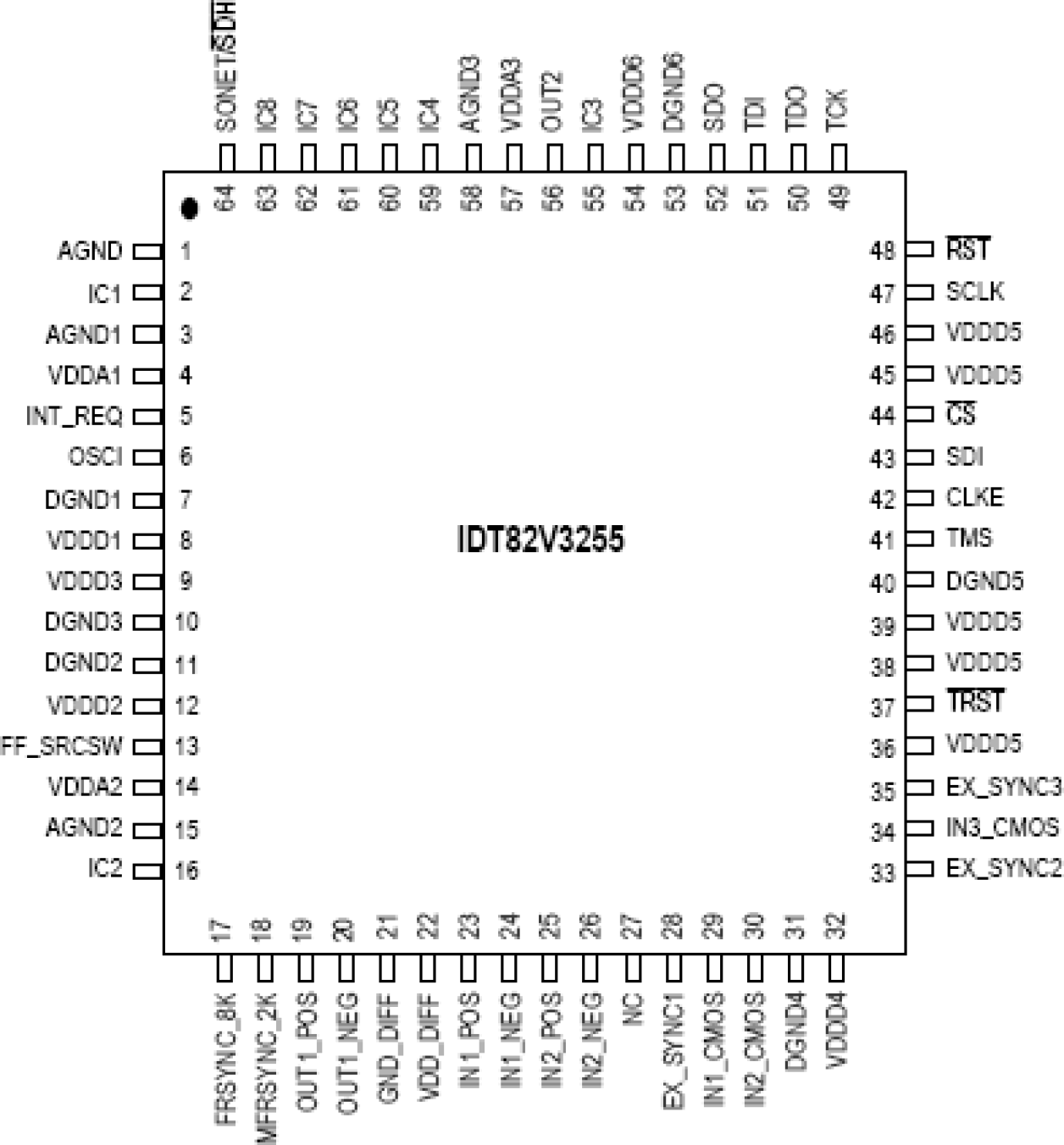
| Pkg. Type: | TQFP |
| Pkg. Code: | PPG64 |
| Lead Count (#): | 64 |
| Pkg. Dimensions (mm): | 10.0 x 10.0 x 1.4 |
| Pitch (mm): | 0.5 |
环境和出口类别
| Pb (Lead) Free | Yes |
| Moisture Sensitivity Level (MSL) | 3 |
| ECCN (US) | |
| HTS (US) |
产品属性
| Pkg. Type | TQFP |
| Lead Count (#) | 64 |
| Pb (Lead) Free | Yes |
| Carrier Type | Reel |
| App Jitter Compliance | Stratum 3, Stratum 4, Stratum 4E, SMC, ITU, Telcordia |
| Core Voltage (V) | 3.3 |
| Hitless Protection | Yes |
| Input Freq (MHz) | 0.002 - 622.08 |
| Input Type | LVCMOS, LVTTL |
| Inputs (#) | 5 |
| Length (mm) | 10 |
| MOQ | 1000 |
| Moisture Sensitivity Level (MSL) | 3 |
| Output Banks (#) | 3 |
| Output Freq Range (MHz) | 0.001 - 622.08 |
| Output Signaling | LVCMOS, LVTTL, LVDS, LVPECL |
| Output Type | LVCMOS, LVTTL, LVDS, LVPECL |
| Output Voltage (V) | 3.3 |
| Outputs (#) | 3 |
| Package Area (mm²) | 100 |
| Pb Free Category | e3 Sn |
| Pitch (mm) | 0.5 |
| Pkg. Dimensions (mm) | 10.0 x 10.0 x 1.4 |
| Qty. per Carrier (#) | 0 |
| Qty. per Reel (#) | 500 |
| Reel Size (in) | 13 |
| Requires Terms and Conditions | Does not require acceptance of Terms and Conditions |
| Tape & Reel | Yes |
| Temp. Range (°C) | 0 to 70°C |
| Thickness (mm) | 1.4 |
| Width (mm) | 10 |
| 已发布 | No |
有关 82V3255 的资源
描述
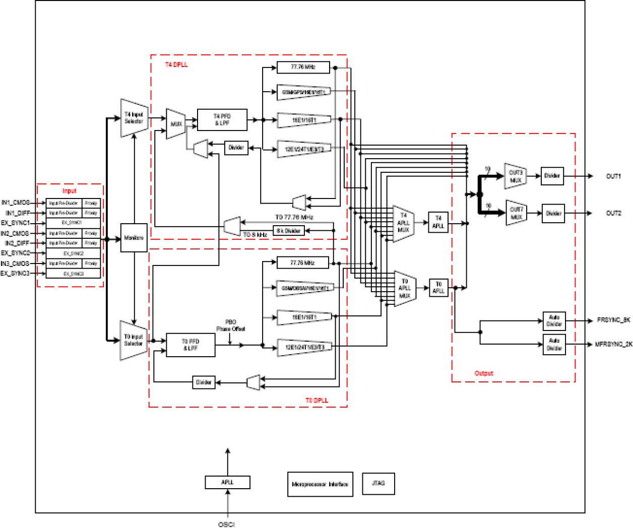
The 82V3255 is an integrated, single-chip solution for the Synchronous Equipment Timing Source for Stratum 3, SMC, 4E and 4 clocks in SONET / SDH equipments, DWDM and Wireless base station, such as GSM, 3G, DSL concentrator, Router and Access Network applications. The device supports three types of input clock sources: recovered clock from STM-N or OC-n, PDH network synchronization timing and external synchronization reference timing. Based on ITU-T G.783 and Telcordia GR-253-CORE, the device consists of T0 and T4 paths. The T0 path is a high quality and highly configurable path to provide system clock for node timing synchronization within a SONET / SDH network. The T4 path is simpler and less configurable for equipment synchronization. The T4 path locks independently from the T0 path or locks to the T0 path. An input clock is automatically or manually selected for T0 and T4 each for DPLL locking. Both the T0 and T4 paths support three primary operating modes: Free-Run, Locked and Holdover. In Free-Run mode, the DPLL refers to the master clock. In Locked mode, the DPLL locks to the selected input clock. In Holdover mode, the DPLL resorts to the frequency data acquired in Locked mode. Whatever the operating mode is, the DPLL gives a stable performance without being affected by operating conditions or silicon process variations. If the DPLL outputs are processed by T0/T4 APLL, the outputs of the device will be in a better jitter/wander performance. The device provides programmable DPLL bandwidths: 0.1 Hz to 560 Hz in 11 steps and damping factors: 1.2 to 20 in 5 steps. Different settings cover all SONET / SDH clock synchronization requirements. A high stable input is required for the master clock in different applications. The master clock is used as a reference clock for all the internal circuits in the device. It can be calibrated within ±741 ppm. All the read/write registers are accessed through a serial microprocessor interface. The device supports Serial microprocessor interface mode only.

