概述
描述
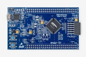
The EK-RX671 is the evaluation kit for the RX671 MCU, providing an efficient tool to evaluate the RX671 MCU. This kit comes with all the hardware and software needed to start evaluation immediately after unboxing.
The EK-RX671 enables debugging key functions of the RX671. In addition, it could be combined with various expansion boards quickly to easily expand the board's functionality.
This board features:
- Hardware and software ready for evaluation right out of the box
- On-board debugger (E2 OB): program writing and debugging are possible simply by connecting the board to a PC via USB cable.
- Ready-to-use software package includes peripheral function drivers, middleware, and guidance documentation.
- Ability to develop prototypes for a wide range of requirements.
- On-board popular ecosystem connectors: easily integrate with expansion boards such as sensor, wireless, LCD, motor boards, etc, enabling to develop wide range of application quickly.
- On-board HMI application target function: 2 capacitive touch buttons, Audio Interface with MEMS micros and 3.5mm headphone jack enable to evaluate HMI functions
- Rich external memory expansion function: 64Mb QSPI Flash, 128Mb 16-bit SDRAM, MicroSD Slot enable expanding memory easily
- Multiple power options to enhance power supply flexibility to meet various needs.
Getting Started
Developing Embedded Application
The software development to evaluate RX671 MCU’s function could be started immediately using the e2 studio IDE and the RX software package that includes peripheral function drivers, middleware, and usage documentation.
- Get familiar with EK-RX671 through the Quick Start example project –The Quick Start example project shows:
- Communication between EK-RX671 and Host PC through USB to Serial interface
- Control User LEDs via User Buttons
- Quad-SPI Flash Read/Write Operation via QSPI
- Start with one of the application projects – Choose from application projects to learn about the different peripherals of the RX671 MCU Group. The number of projects will grow progressively over time. These example projects can be downloaded from “Design & Development” and serve as excellent starting points for you to develop your custom applications.
- Audio Output/Input project via Serial Sound Interface (SSIE)
- HMI application project demonstrating SPI LCD display and Cap Touch functions.
Building a Custom Hardware
- Start by building a functional prototype – Utilize the EK-RX671 board with your choice of hundreds of popular ecosystem add-ons.
- Build custom hardware – Develop custom hardware by referring to the design and manufacturing information provided in the EK-RX671 Design Package.


特性
- Ecosystem & System Control
- USB Full Speed host and device
- USB-Serial Converter Interface
- Multiple 5V input sources
- USB (Debug, Full Speed, USB/Serial Converter)
- External power supply
- E2 OB on-board programmer and debugger
- Debug modes
- Debug On-board (FINE) – via E2 OB
- Debug In (JTAG or FINE Interface)
- User LEDs and buttons
- Three user LEDs (red, blue, green)
- Power LED (white) indicating availability of regulated power
- Debug LED (yellow) indicating the debug connection
- Two user buttons
- One reset button
- Five most popular ecosystem expansions
- MikroElektronika™ mikroBUS connector
- SparkFun® Qwiic® connector
- Two SeeedGrove® system (I2C and Analog) connectors
- Two Digilent Pmod™ (SPI/UART/I2C) connectors
- Arduino™ (Uno R3) connector
- MCU mode configuration switch
- Special Features
- Audio Interface
- 128Mb SDRAM
- 64Mb External Quad-SPI Flash
- MicroSD Card Slot
- 2 Capacitive Touch Buttons
- MCU Native Pin
- R5F5671EHDFB MCU
- 120MHz, RXv3 core
- 2MB Code Flash, 384KB SRAM
- 144 pins, LFQFP package
- Native pin access through male pin headers
- MCU current measurement
- Kit Contents: EK-RX671 board, Micro USB device cable (type-A male to micro-B male), Micro USB host cable (type-A female to micro-B male)
应用
文档
|
|
|
|
|---|---|---|
| 类型 | 文档标题 | 日期 |
| 快速入门指南 | PDF 1.58 MB 日本語 | |
| 手册 - 开发工具 | PDF 1.54 MB 日本語 | |
| PCB 设计文件 | EK-RX671 v1 - Design Package
|
|
| 应用说明 |
PDF
3.28 MB
The DA16200/DA16600 is a Wi-Fi module that supports diverse connected applications with efficiency, security, and enhanced user experience on Renesas RX Family microcontrollers. This application note describes the usage of DA16200/DA16600 PMOD module, including API information, configuration guidelines, which conforms to the Firmware Integration Technology (FIT) standard and step-by-step instructions for executing demo applications with TCP, MQTT, and HTTP protocols on RX MCU boards.
|
|
| 应用说明 |
PDF
2.19 MB
The DA14531/DA14535 is a Bluetooth low energy SoC that supports diverse connected applications with efficiency, security, and enhanced user experience on Renesas RX Family microcontrollers. This sample package includes an application note describing the usage of the DA14531/DA14535 PMOD module, which conforms to the Firmware Integration Technology (FIT) standard, the DA1453x BLE FIT module itself, and demo applications on CK-RX65N v2 in both peripheral and central roles.
|
|
| 应用说明 |
PDF
856 KB
日本語
AI 生成的摘要:
The document explains audio input/output programming using the RX671 microcontroller's SSIE function and Firmware Integration Technology (FIT) compatible SSI module. It details three operational modes: sine wave output, on-board microphone audio input/output, and audio player mode. The sine wave mode generates set-frequency PCM data output via SSIE and DMAC. The microphone mode captures audio from the on-board MEMS microphone, processes it, and outputs via Audio Codec. Sampling rates, data bit lengths, and application examples such as alarms, voice recording, and speech recognition are provided. The evaluation board EK-RX671 is used for testing and demonstration.
|
|
| 应用说明 |
PDF
1.39 MB
日本語
AI 生成的摘要:
The document explains how to execute programs stored in serial ROM using the QSPIX module's XIP mode on the RX671 Group. It covers enabling and terminating XIP mode, which accelerates ROM read operations by skipping instruction code reception. The prefetch function improves execution speed by continuously buffering data from the serial ROM. The document provides three sample programs: an application program with code in serial ROM, and two writer programs that write data to the serial ROM via different methods. It also details hardware configurations, software build settings, and debugging procedures to support program execution from serial ROM.
|
|
| 应用说明 |
PDF
1.59 MB
日本語
AI 生成的摘要:
The document explains how to perform read and write operations on 128 Mbit SDRAMs using the SDRAM controller (SDRAMC) in RX Family MCUs such as RX65N, RX72M, RX72N, and RX671. It covers initialization sequences, timing configurations, and verification methods using sample codes. The document details SDRAM specifications from Micron and Alliance Memory, including timing parameters and refresh cycles. It also provides guidance on porting sample codes with or without Smart Configurator to other RX Family MCUs, along with hardware and software setup instructions.
|
|
| 应用说明 |
PDF
1.90 MB
日本語
AI 生成的摘要:
The GUI sample program demonstrates how to develop a graphical user interface using a serial TFT-LCD display combined with the emWin graphics library. It covers key emWin functions such as window management, widgets, memory devices, animations, and screen transitions via touch keys. The program includes multiple screens like Home, RX Logo Display, Air Conditioning Control, Image Display, and Font Display. It requires an SPI-compatible TFT-LCD and the EK-RX671 target board. The document details software and hardware configurations, project structure, and resource usage to facilitate GUI development on RX671 microcontrollers.
|
|
| 报告 | PDF 187 KB 日本語 | |
10 项目
|
||
设计和开发
软件与工具
软件与工具
| Software title
|
Software type
|
公司
|
|---|---|---|
| C/C++ Compiler Package for RX Family [CC-RX] C/C++ Compiler Package for RX Family [IDE: CS+, e² studio, High-performance Embedded Workshop]
|
Compiler/Assembler | 瑞萨电子 |
| 快速连接平台 快速连接平台通过提供兼容的硬件和软件构建模块,实现快速原型设计。
|
Software and Hardware Development Tools | 瑞萨电子 |
| e² studio - Information for the RX Family Eclipse-based Renesas integrated development environment (IDE).
|
IDE and Coding Tool | 瑞萨电子 |
| Renesas Flash Programmer (Programming GUI) 闪存编程软件【支持 MCU/MPU 和设备:RA、RE、RX、RL78、RH850、RISC-V MCU, Renesas Synergy、DA1453x、DA1459x、DA1469x、DA1470x、DA148xx、电源管理、Renesas USB Power Delivery 系列、电机驱动器/执行器驱动器 IC、V850、78K0R、78K0】
|
Programmer (Unit/SW) | 瑞萨电子 |
| QE for Capacitive Touch: Development Assistance Tool for Capacitive Touch Sensors In developing embedded system using the capacitive touch sensor of MCUs, you can easily setup initial configurations of the touch interface as well as process the tuning of sensors, and reduce development time. [Plugin for Renesas IDE "e2 studio"] [Standalone Version] [Support MCU/MPU:RA, RL78, RX, Renesas Synergy™]
|
Solution Toolkit | 瑞萨电子 |
| PG-FP6 Flash memory programmer [Programming software: Dedicated GUI-based software, the "FP6 Terminal"] [Support MCU/MPU and devices: RA, RE, RX, RL78, RH850, RISC-V MCU, Renesas Synergy, Power Management, Renesas USB Power Delivery Family, ICs for Motor Driver/Actuator Driver, SuperH RISC engine, V850, 78K, R8C]
|
Programmer (Unit/SW) | 瑞萨电子 |
| E2 emulator Lite [RTE0T0002LKCE00000R] On-chip debugging emulator. Also available as a flash memory programmer. [Support MCU/MPU: RA, RE, RL78, RX, RISC-V MCU]
|
Emulator | 瑞萨电子 |
| E2 emulator [RTE0T00020KCE00000R] On-chip debugging emulator. Also available as a flash memory programmer. [Support MCU/MPU: RA, RE, RH850, R-Car D1, RL78, RX, RISC-V MCU]
|
Emulator | 瑞萨电子 |
8 项目
|
||
样例程序
样例程序
筛选
|
||
|---|---|---|
| 类型 | 文档标题 | 日期 日期 |
| 示例代码 | RX Family US159-DA16XXXMEVZ Wi-Fi Control Module Using Firmware Integration Technology Rev. 1.41 - Sample Code
[Software=RX Driver Package|V1.50],[Toolchains=CC-RX|V3.07.00;GNURX|14.2.0.202505]
ZIP
31.79 MB
应用:
工业, 消费电子产品
Compiler:
CC-RX, GNURX
Function:
Communication Interface
IDE:
e2 studio
The DA16200/DA16600 is a Wi-Fi module that supports diverse connected applications with efficiency, security, and enhanced user experience on Renesas RX Family microcontrollers. This application note describes the usage of DA16200/DA16600 PMOD module, including API information, configuration guidelines, which conforms to the Firmware Integration Technology (FIT) standard and step-by-step instructions for executing demo applications with TCP, MQTT, and HTTP protocols on RX MCU boards.
|
|
| 示例代码 | RX Family US159-DA1453xEVZ BLE Control Module Using Firmware Integration Technology Rev. 1.70 - Sample Code
[Software=RX Driver Package|V1.50],[Toolchains=CC-RX|V3.07.00]
ZIP
121.93 MB
应用:
工业, 消费电子产品
Compiler:
CC-RX
Function:
Communication Interface
IDE:
e2 studio
The DA14531/DA14535 is a Bluetooth low energy SoC that supports diverse connected applications with efficiency, security, and enhanced user experience on Renesas RX Family microcontrollers. This sample package includes an application note describing the usage of the DA14531/DA14535 PMOD module, which conforms to the Firmware Integration Technology (FIT) standard, the DA1453x BLE FIT module itself, and demo applications on CK-RX65N v2 in both peripheral and central roles.
|
|
| 示例代码 | RX Family Audio Input/Output Program Using SSIE Rev.1.01
[Toolchains=CC-RX|V3.06.00]
ZIP
13.36 MB
日本語
Compiler:
CC-RX
Function:
Application Example, Communication Interface
IDE:
e2 studio
|
|
| 示例代码 | RX671 Group Example of Program Execution from Serial ROM Using QSPIX XIP Mode Rev.2.10
[Toolchains=CC-RX|V3.04]
ZIP
64.43 MB
日本語
Compiler:
CC-RX
Function:
Driver or Library, Memory
IDE:
e2 studio
|
|
| 示例代码 | RX Family Read/Write Operations in SDRAM Using the SDRAMC Rev.1.10 - Sample Code
[Toolchains=CC-RX|V3.02]
ZIP
41.60 MB
日本語
Compiler:
CC-RX
Function:
Driver or Library, Memory
IDE:
e2 studio
|
|
| 示例代码 | RX Family GUI Sample Program using Serial LCD and emWin Library
[Software=RX Driver Package|V1.39],[Toolchains=CC-RX|V3.05.00]
ZIP
105.20 MB
日本語
Compiler:
CC-RX
Function:
Application Example, Communication Interface
IDE:
e2 studio
|
|
| 示例代码 | EK-RX671 Quick Start Example Project
|
|
7 项目
|
||
相关评估板和套件
开发板与套件
RX671 目标板
RX671 目标板为 RX671 MCU 的评估、原型制作和开发提供一个切入点。 此外,由于此目标板集成了调试器,您可以将其用于自己的应用设计,而无需进一步投资开发工具。 这款产品提供通孔形式的引脚接头,可连接所有 MCU 的信号引脚,从而可以使用面包板轻松地进行原型设计。 此外,此板还具有 Pmod 接口,可通过连接 Wi-Fi 模块、传感器模块等来增强功能。
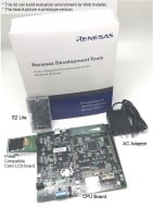
Renesas Starter Kit+ for RX671
The Renesas Starter Kit+ for RX671 is the perfect starter kit for developers who are new to the RX671 (Code Flash 2MB, Pin Count 144-pin). The kit includes an LCD display module and an on-chip debugging emulator. Download the integrated development environment (CS+ version and e² studio version)... 阅读详情
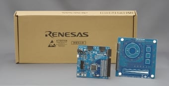
RX671 电容式触摸评估系统
RX671 电容式触控评估系统使用户能够轻松评估瑞萨电子提供的触控解决方案。 您可以使用套件中的电路板和软件即刻开始评估,开箱即用。
产品配置
- RX671 CPU 板
- 触摸应用板
- 自电容评估板设有三种基础的电容触控功能:开关、滑条和滚轮
产品选项
| Part Number | Status | Stock | Budgetary Price (USD) | Sampleable |
|---|---|---|---|---|
| RTK5EK6710S00001BE | Active | In Stock | 1u | $78.04 | Available |
视频和培训
Certifications
The EK-RX671 meets the following certifications/standards. Refer to the EK-RX671 user manual for the disclaimer, precautions, and more details on the certifications.
EMC/EMI Standards
- FCC Notice (Class A) – Part 15
- Innovation, Science and Economic Development Canada ICES-003 Compliance: CAN ICES-3 (A)/NMB-3(A)
- CE Class A (EMC Directive 2004/108/EEC)
- Taiwan Chinese National Standard 13438, C6357 compliance, Class A limits
- Australia/New Zealand AS/NZS CISPR 32:2015, Class A
Material Selection, Waste, Recycling, and Disposal Standards
- EU RoHS
- China SJ/T 113642014, 10-year environmental protection use period.
Safety Standards
- UL 94V-0


