特性
- Gain bandwidth product: 4.0GHz
- Input voltage noise: 0.85nV/√(Hz)
- Differential slew rate: 5,600V/µs
- 2VP-P, 2-tone IM3 (200Ω) 100MHz: -109dBc
- Supply voltage range: 3.0V to 4.2V
- Quiescent power (3.3V supply): 115mW

描述
The ISL55210 is a very wide band, fully differential amplifier (FDA) intended for high dynamic range ADC input interface applications. This voltage feedback FDA design includes an independent output common mode voltage control. At the lowest quiescent power (115mW), the ISL55210 offers a 4.0GHz gain bandwidth product with a very low input noise of 0.85nV/√(Hz). In a balanced differential I/O configuration, with 2VP-P output into a 200Ω load configured for a gain of 15dB, the IM3 terms are <-100dBc through 110MHz. With a minimum operating gain of 2V/V (6dB), the ISL55210 supports a wide range of higher gains with minimal BW or SFDR degradation. Its ultra-high differential slew rate of 5,600V/µs ensures clean large signal SFDR performance or a fast settling step response. The ISL55210 requires only a single 3.3V (max 4.2V) power supply with a 35mA typical quiescent current. This industry-leading low-current solution can be further reduced when needed using the optional power shutdown to <0.4mA supply current. External feedback and gain setting resistors give maximum flexibility and accuracy. A companion device, the ISL55211, includes on-chip feedback and three possible gain setting connections where an internally fixed gain solution is preferred. The ISL55210 is available in a leadless, 16 Ld TQFN package and is specified for operation over the -40 °C to +85 °C ambient temperature range.
产品参数
| 属性 | 值 |
|---|---|
| Channels (#) | 1 |
| Temp. Range (°C) | -40 to +85°C |
| Bandwidth (MHz) | 2200 |
| Gain Min | 2 |
| Offset Voltage (Max) (mV) | 1.4 |
| IBIAS (nA) | 50000 |
| IOUT (A) | 0.045 |
| CMRR (dB) | 75 |
| PSRR (db) | 90 |
| Rail-to-Rail Input | No |
| Rail-to-Rail Output | No |
| IS per Amp (mA) | 35 |
| Noise VN (nV/√Hz) | 0.85 |
| Single Supply Voltage Range (V) | 3 - 4.2 |
| Slew Rate (V/µs) | 5600 |
| VOUT (V) | 3.8 |
| VS (Min) (V) | 3 |
| VS (Max) (V) | 4.2 |
| 2nd Harmonic (dB) | -105 |
| 3rd Harmonic (dB) | -120 |
| AVOL (dB) | 100 |
| Topology [Rail 1] | FDA |
| Enable | Yes |
| Output Headroom (V) | 1 |
| Distortion Conditions | 2Vpp, 20MHz |
| Qualification Level | Standard |
封装选项
| Pkg. Type | Pkg. Dimensions (mm) | Lead Count (#) | Pitch (mm) |
|---|---|---|---|
| TQFN | 3.0 x 3.0 x 0.75 | 16 | 0.5 |
应用
- Low power, high dynamic range ADC interfaces
- Differential mixer output amplifiers
- SAW filter pre/post driver
- Differential Comms-DAC output drivers
Renesas Boards & Kits
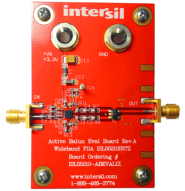
High-Speed Differential Amplifier in an Active Balun Configuration Evaluation Board
This relatively simple board is intended to provide a quick means to test the performance of the active balun configuration using the ISL55210 wideband, fully differential amplifier (FDA). While all wideband, voltage feedback (VFA), fully differential amplifiers can perform a single-ended input... 阅读详情
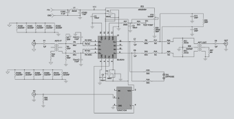
Wideband, Low-Power, Ultra-High Dynamic Range Differential Amplifier Evaluation Board
The ISL55210IRTZ-EVALZ evaluation board is used to evaluate the ISL55210 TQFN wideband, low-power, ultra-high dynamic range differential amplifier. The ISL55210 wideband differential I/O amplifier is intended principally as the last stage interface to high-performance 12 to 16-bit... 阅读详情
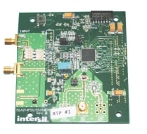
Ultra-Low Power Broadband 8- to 14-Bit Data Acquisition Kit
Quickly evaluate the amplifier, filter, and analog-to-digital converter (ADC) signal chain's total performance in your application. Pairing with Renesas' ADC KMB-001LEVALZ motherboard, this amplifier + ADC daughterboard provides a 100kHz to 100MHz flat data acquisition channel requiring only... 阅读详情
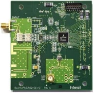
Ultra-High Performance Broadband 12- to 16-Bit Data Acquisition Pkit
This ISLA214P50-55210EV1Z is an evaluation platform featuring Renesas' ultra-high, dynamic range, fully differential amplifier (FDA), the ISL55210, and the high-speed, high-performance, 14-bit, 500MSPS ADC, the ISLA214P50. In the delivered configuration, it offers a full signal path reference... 阅读详情
