跳转到主要内容

概览

描述

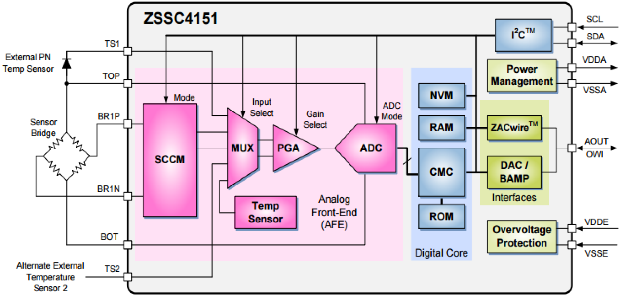
ZSSC4151 是一款 CMOS 集成电路,专用于电阻电桥传感器信号的放大及传感器特性化校正。 该器件通过内部 16 位 RISC 微控制器运行校正算法,实现传感器偏移、灵敏度、温度漂移和非线性度数字补偿。所有校正系数均存储在集成 EEPROM 中。 ZSSC4151 几乎可适配所有电阻电桥传感器类型。 测量值可通过模拟电压输出端和可选的数字 I2C 接口或 ZACwire™ 接口(也称为单线接口 (OWI))提供。 数字接口可用于简单的 PC 控制校准程序,将整套校准系数编程到片载 EEPROM 中。 ZSSC4151 和校准设备可进行数字通信,因此噪声灵敏度大大降低。 数字校准有助于保持较低的装配成本,因为不需要外部设备或修整。

特性

  • 对传感器偏移、灵敏度、温度漂移和非线性进行数字补偿
  • 几乎可适配所有全桥或半桥传感器
  • 模拟增益 200 倍,使用数字变焦选项可支持低至 1mV/V 量程的传感器
  • 输出选项:比例式 12 位模拟电压输出(如 5-95% 或 10-90%),带自由可调钳位功能或 ZACwire™ 数字单线接口(OWI)
  • 温度补偿:内部或外部二极管、桥路外接串联电阻或 RTD
  • 通过内部电压实现传感器偏置
  • 所有模块引脚(VDDE、VSSE 和 AOUT)均可承受最高 40V 的高压并具有反极性保护
  • 最大电源电流:7mA
  • AOUT 短路保护
  • 通过用户定义寄存器实现可追溯性

产品对比

应用

文档

类型 文档标题 日期
数据手册 登录后下载 PDF 729 KB
数据手册 登录后下载 PDF 565 KB
指南 7Z 1.21 MB
3 项目

设计和开发

开发板与套件

模型

ECAD 模块

点击产品选项表中的 CAD 模型链接,查找 SamacSys 中的原理图符号、PCB 焊盘布局和 3D CAD 模型。如果符号和模型不可用,可直接在 SamacSys 请求该符号或模型。

Diagram of ECAD Models

产品选项

当前筛选条件

支持

支持社区

支持社区

在线询问瑞萨电子工程社群的技术人员,快速获得技术支持。
浏览常见问题解答

常见问题

浏览我们的知识库,了解常见问题的解答。
提交工单

提交工单

需要咨询技术性问题或提供非公开信息吗?

支持社区

  1. ZSSC4151C Evaluation Software

    管理您好,我购买了ZSSC4151C芯片,请问芯片配套的ZSSC4151C软件在哪里获取?

    2024年12月6日
  2. ZSSC41xx Evaluation Software v3.4.0.0

    管理员您好,我购买了ZSSC4151C芯片,与开发套件,我在官网申请软件下载; 目前已经5天了,访问权限仍然没有通过。 请协助一下 ;

    2024年12月4日

视频和培训

The ZSSC4151 is a CMOS integrated circuit for highly accurate amplification and sensor-specific correction of resistive bridge sensor signals. Digital compensation of sensor offset, sensitivity, temperature drift, and non-linearity is accomplished via an internal 16‑bit RISC microcontroller running a correction algorithm, with calibration coefficients stored in an integrated EEPROM.

Related Resources

TRANSCRIPT

Hi, I'm Chris Anderson at the E.U Web tech lab and today we'll discuss IDT's ZSSC415X family of parts which are automotive sensor signal conditioners that provide an analog output with the benefits of a digital core. The ZSSC4151 is the first product in the family and features a 16 bit risk MCU, interfaced to an analog front end with 12 to 18 bits of resolution and which can be used within any type of bridge sensor.

The digital core enables a correction algorithm to internally handle compensation for factors such as thermal drift, non-linearity and sensor offset. These factors are stored in the on chip EPROM. Calibration is also controlled digitally, which reduces noise sensitivity and eliminates the need for trimming.

Once the measured value's digitally corrected, it is then output as an analog signal through a 12 bit deck or over the serial interface. The ZSSE4151 is AEC-Q100 qualified and targeted at automotive applications, including pressure sensors and temperature sensors. The evaluation kit consists of a communication board, the sensor signal conditioner board and a board with a potentiometer for simulating sensor input.

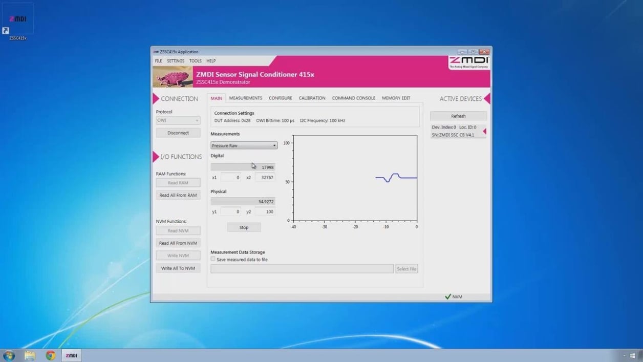
So once you've connected the board for the evaluation kit and then connected via USB to your computer, open the ZSSC415X application. On the far right side you should see an entry here that indicates your device is connected properly to the computer and recognized by the software. The first thing you need to do is load the GUI configuration file and accept all the prompts as you go and then load the NVM dump file and then 'write all to NVM'. Once that's complete you'll see the green checked mark down here with NVM next to it indicating that data was successfully written.

Now we can start collecting data and using this simulated pressure sensor which is just a potentiometer, you can see that as I adjust it, the data being reported in the program adjusts as well. And you can also go look at temperature data which right now it says it's about 19 degrees in the room which...well that is cold, I do believe that's correct because it is quite chilly in the room. And you can also look at the raw pressure data.

Now this hasn't been calibrated so if we click on the calibration tab, verify that all your settings are as you see them here and then what we'll do is go down to P1 and we'll spin the potentiometer fully counterclockwise, click 'Acquire data' and we'll go to P2 and then turn that fully clockwise so that it's at its maximum value and acquire data again and then you can click 'Calculate' and in this window down here you can see the calculations that are being done.

If you scroll all the way to the bottom, there's an output and if you hover over that, you can see the full output of the calibration. If we write coefficients to NVM, that will write all the data to the non-volatile memory and then if we come back here to 'main' and start collecting data again, you'll now see that since I left it at its maximum and back here our target min and our target max were 90% and 10%, that data will show up as the 90% value.

And as we adjust down, this should put me in about half way, so I should be setting it about 50% and as I rotate counterclockwise, if I pass the mid-point, that will put me at about 50% and then as I continue counterclockwise, that should bring me down to 10%. One of the things that I really like about ZMDI's boards is you can see on the sensor conditioner board. You have full access to all the pins so you can hook up your own external sensors, you can hook up your own instrumentation so that you can really truly evaluate the board.

And on the software side and this is very much in ZMDI's nature, they give you access to more settings than you can possibly imagine and so there's really no limit in this evaluation kit for evaluating the ZMDI ZSSC415X family of products.

IDT ZSSC4151 provides users needing an analog signal with the benefits of digital calibration and compensation. For more information, visit idt.com.