- |
- |
Device Group Additions
Overview
The device group addition license tool is a product for adding device groups to be selected with the E10A- USB emulator. The device group selected (installed) at the time of purchase can not be changed once it is selected, so please use this license tool to add a device group.
Note that this product available for HS0005KCU01H and HS0005KCU02H but not for HS0005KCU14H.
Initial Purchase License
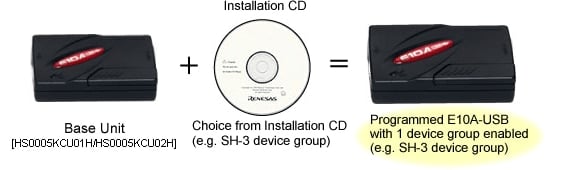
The E10A-USB is supplied with the entitlement to install any ONE of the available Device Groups on a one-time-only (OTP) basis using the Installation CD (e.g. SH-3 Device Group). Users should ensure they pick the correct device group to install. Please refer to the list of supported devices.
Once the installation has taken place the E10A USB will support devices in that group only, unless a Device Group Additions is purchased. To add further device groups, the user can purchase Device Group Additions software (License Tool for Device Group Additions) for the required Group.
If a new device which is included in the device group you installed to your E10A-USB is released, downloading the latest emulator software will add the new device to your E10A-USB.
Periodically new devices will be added to device groups, if an E10A-USB is programmed to support SH-3 for instance and a new SH-3 device is added to the list of devices supported by E10A-USB, Renesas will make available a patch to update the E10A-USB free of charge.
Subsequent Purchase License
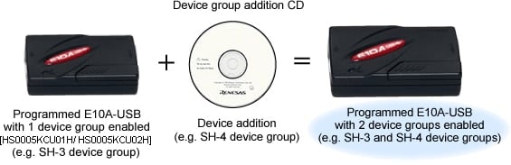
If the user subsequently wishes to upgrade their E10A-USB to support an additional device group, Device Group Additions (License Tool for Device Group Additions) are available as additional purchases (subject to release schedule). The Device Addition is supplied as a CD-ROM with the desired Group software. This is used in conjunction with the original E10A-USB unit.
- You do not need to purchase a Device Group Addition (License Tool for Device Group Additions) to support the first device group, the E10A-USB is shipped with an installer that allows the user to support any one of them. Our range of Device Group Additions is for adding subsequent device groups to an existing system.
- Device Group Additions are prepared for each device group. It can be purchased from your Renesas supplier or distributor by ordering the appropriate part number from the table below and are delivered in on CD-ROM.
- One license is available for one E10A-USB.
- If a user has purchased a Device Group Addition or selected a Device Group at initial installation then there is no need to purchase a new Device Group Addition to add new devices within the same Device group even if they are released at a later date.
- Update patches can be downloaded from the Download site or requested from your Tools Product Support team.
Part Numbers of the License Tools
| Device Group | Part Number |
|---|---|
| H8S | HS2339KCU01SR |
| H8SX | HS1527KCU01SR |
| SH-2 | HS7047KCU01SR |
| SH-2A | HS7206KCU01SR |
| SH-3 | HS7729KCU01SR |
| SH-Mobile | HS7290KCU01SR (Discontinued product) |
| New_SH-Mobile | HS7318KCU01SR |
| SH-4 | HS7751KCU01SR |
| SH-4A | HS7780KCU01SR |
For the supported devices, refer to MPUs and MCUs Supported by the E10A-USB Emulator V.3.06 Release 00 (PDF | English, 日本語).
How to Add Devices
When you add subsequent device groups to E10A-USB; install "License Tool for Device Group Additions" on your PC, and use it in accordance with the procedure below.
Important: Do not use "License Tool for Device Group Additions" if no device group has been set up in E10A-USB.
Procedure
- Step 1
- Open the sliding switch cover and check that the switch ( SW1 ) for setting the emulator is turned to "1". For the positions of the parts, refer to 3.8 Setting the DIP Switches, in the E10A-USB emulator User's Manual.
- Step 2
- Select [ Renesas ] -> [ License Tool for E10A-USB ] -> [ SHxxxx ( H8S/xxxx ) Device Group ] from [ Programs ] in the [ Start ] menu. "License Tool for Device Group Additions" is activated.
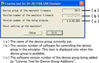
Notes
- If "-----" is shown in (a), no device group is set in E10A-USB. Do not use "License Tool for Device Group Additions".
- Use "License Tool for Device Group Additions" only when "-.-.--.---" is shown in (b).
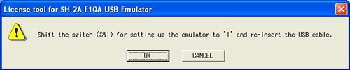
- If the following error message is displayed, the host computer is not connected to the emulator or the setup switch ( SW1 ) is turned to "0". In case the setup switch ( SW1 ) is turned to "0", set it to "1" and connect the USB cable again.
- Step 3
- Click the [ Setup ] button. When the following dialog box is displayed, addition of a device group is completed.
Notes
- When [ Add New Hardware Wizard ] is displayed, select the [ Search for the best driver for your device. ( Recommended ) ] radio button and then the [ Specify a location ] check box to select the path to be searched for drivers. The location must be specified as < Drive > : \ DRIVERS. ( < Drive > is the CD drive letter.)
- When using with Windows®XP, a dialog box will be displayed to show the disconnection of the USB. However, this is not a problem.
- Do NOT turn off the host computer or disconnect the USB cable while setting up the emulator or the emulator may be damaged.
After completing addition of a device group, set up E10A-USB.
Debug MCU Board (Discontinued product)
Support for this product is limited to customers who have already adopted these products.
Debug MCU Board for SuperH Family
Overview
"Debug MCU board" is an optional board to use the E10A-USB on-chip debugging emulator under the circumstance of developing systems employing MCUs without the user-debugging interface (H-UDI) function nor AUD (Advanced User Debugger) function. It also enables the E10A-USB emulator to work as a simple in-circuit emulator, which leads users to the effective development. The available debugging functions are as follows: executing the program, generating a break, viewing or changing the memory content, measuring performance, acquiring a trace, and so on. In addition, users can use all pins of the MCU (the emulator does not occupy any pins of the MCU).
Specifications
| Core of Supported MCUs | SH-2 | SH-4A | |
|---|---|---|---|
| Power Supply to Debug MCU Board | The following two ways are available.
| To supply externally via the power terminal on the Debug MCU board. (5V) | |
| Connection | Target Board | Plug into the IC socket on the target board. | (same as the left) |
| E10A-USB Emulator | H-UDI (without AUD) : 14-pin, H-UDI (with AUD) : 36-pin | (same as the left) | |
| External Dimension | Body | 80mm x 85mm | 105mm x 135mm |
| Cable | 150mm (flexible cable) | 267mm (flexible cable) | |
| Cable Head | 35mm x 40mm | 35mm x 58.5mm | |
| Bundled Accessory | Applicable IC Socket for MCU package (qty.1) Power cable | Applicable IC Socket plug for MCU package (qty.1) Power cable | |
| System Configuration | 图像  | 图像  | |
Specifications in Using With Debug MCU Board
Debug MCU Board for SH-2 Core
| When Used as On-Chip Debugger | Only E10A-USB Emulator Note1 | E10A-USB Emulator With Debug MCU Board for SH-2 Core | |
|---|---|---|---|
| Connection to User Board | H-UDI port connector | IC socket | |
| H-UDI Terminals | Used exclusively by emulator | All user-pin functions are available. | |
| Trace Function | Built-in Trace | lens (4 branches) | lens (1024 cycles) |
| AUD Trace Note2 | - | lens Max. 64K events (In case of acquiring only branch trace info, 32K branches in max is available.) | |
| Performance Measurement | - | lens | |
| User's System | Required | lens Available to debug without user's system | |
lens Available | — Not Available
Notes:
- The architecture of only E10A-USB is NOT available for SH7147 Series.
- Not usable with HS0005KCU01H.
| When Used as In-Circuit Emulator | E200F Emulator (With EVA-Chip Unit) | E10A-USB Emulator With Debug MCU Board for SH-2 Core | |
|---|---|---|---|
| Connection to User Board | IC socket | (same as the left) | |
| H-UDI Terminals | All user-pin functions are available. | (same as the left) | |
| Break Function | S/W Break | 1000 points | 255 points |
| On-Chip Break | 10 points | (same as the left) | |
| AUD Break | 8 points | - | |
| Trace Function | Built-in Trace | lens (1024 cycles) | (same as the left) |
| AUD Trace Note1 | lens (256K cycles) | lens Max. 64K events (In case of acquiring only branch trace info, 32K branches in max is available.) | |
| Performance Measurement | lens | (same as the left) | |
| Real-Time Profile | lens | - | |
| C0 Coverage Measurement | lens | - | |
| User's System | Available to debug without user's system | (same as the left) | |
lens Available | — Not Available
Note:
- Not usable with HS0005KCU01H.
Debug MCU Board for SH-4A Core
| When Used as On-Chip Debugger | Only E10A-USB Emulator | E10A-USB Emulator With Debug MCU Board for SH-4A Core | |
|---|---|---|---|
| Connection to User Board | H-UDI port connector | IC socket | |
| Trace Function | Built-in Trace | lens (8 branches) | (same as the left) |
| AUD Trace Note1 | - | lens Max. 64K events (In case of acquiring only branch trace info, 32K branches in max is available.) | |
| User's System | Required | lens Available to debug without user's system | |
lens Available | — Not Available
Note:
- Not usable with HS0005KCU01H.
Supported MCUs and Part Names
SH-2
| Supported MCU | Package Code | Previous Package Code | Debug MCU Board | IC Socket Note1 (Made by Tokyo Eletech Co., Ltd.) | |
|---|---|---|---|---|---|
| Series | Group | ||||
| SH7147 | SH7147 (SH7142) | PLQP0100KB-A | FP-100UV | HS7147EDB01H | NQPACK100SD-ND |
| SH7125 | SH7124 | PLQP0048JA-A | FP-48FV | HS7124EDB01H | NQPACK048SB |
| PVQN0052LE-A | - | HS7124EDB02H | NBSOCKET052SE-RE41N + NWPLUG052SE-RE01 | ||
| SH7125 | PLQP0064KB-A | FP-64KV | HS7125EDB01H | NQPACK064SD-ND | |
| PRQP0064GB-A | FP-64AV | HS7125EDB02H | NQPACK064SA | ||
| PRQP0064GC-A | FP-64HA | ||||
| PVQN0064LB-A | TNP-64BV | HS7125EDB03H | NBSOCKET064SE-RE41N + NWPLUG064SE-RE01 | ||
Note:
- Bundled with Debug MCU Board. (Except for products with " ** ".)
SH-4A
| Supported MCU | Package Code | Previous Package Code | Debug MCU Board | IC Socket Note1 (Made by Tokyo Eletech Co., Ltd.) | |
|---|---|---|---|---|---|
| Series | Group | ||||
| SH7450 | SH7459 Note2 SH7457 Note3 SH7456 SH7455 | PLBG0176GA-A | - | R0E574504PBZ00 + R0E574552CBG00 [User's I/F converter board] | CSPLUG/W176A1513RE01 + BSSOCKET176A1513RE21N** |
| SH7451 SH7450 | PRBG0292GB-A | - | R0E574504PBZ00 + R0E574504CBF10 [User's I/F converter board] | CSPLUG/W292A2017RE01 + BSSOCKET292A2017RE21N** | |
** : Not bundled with Debug MCU Board.
Notes:
- Bundled with Debug MCU Board. (Except for products with "**".)
- Select SH74504_Debug_MCU_BOARD in the E10A-USB window.
- Select SH74552_Debug_MCU_BOARD in the E10A-USB window.
Debug MCU Board for H8S/2400 Series
Overview
"Debug MCU board" is an optional board to use the E10A-USB on-chip debugging emulator in development of systems using pins for user-debugging interface (H-UDI) and alternative ones. Users can use all pins of the MCU (the emulator does not occupy any pins of the MCU).
Specifications
| Item | Description |
|---|---|
| Supported MCU | H8S Family - H8S/2424, 2426, 2426R Group - H8S/2454, 2456, 2456R Group |
| Power Supply to Debug MCU Board | The following two ways of powering are available. (1) To be powered by the target board when it is connected with. (2) 5V or 3.3V to be powered externally via the power connector on the Debug MCU Board when it is used alone. |
| Connection to Target System | Plug into the IC socket on the target board. |
| Connection to E10A-USB Emulator | H-UDI (without AUD) : 14-pin |
| External Dimension | Body : 95mm×45mm |
| Bundled Accessory | Applicable IC Socket for MCU package (qty.1) Power Cable of 600mm long (qty.1) |
| System Configuration | 图像 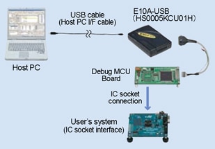 |
Features in Using With Debug MCU Board
| When you use; | Only E10A-USB Emulator | E10A-USB Emulator With Debug MCU Board |
|---|---|---|
| Connection to User Board | via H-UDI port connector | via IC socket |
| H-UDI Terminals | Alternative to the port | All user-pin functions are available. |
Product Part Numbers
| Supported Device | Package Code | Previous Package Code | Debug MCU Board | IC Socket Note1 (Made by Tokyo Eletech Co., Ltd.) |
|---|---|---|---|---|
| H8S/2456xF | PLQP0144KA-A | FP-144LV | R0E424568PFK00 | NQPACK144SD-ND |
| H8S/2454xF | PLQP0120LA-A | FP-120BV | R0E424548PFK00 | NQPACK120SE-ND |
| PLQP0120KA-A | - | R0E424548PFK01 | NQPACK120SD | |
| H8S/2426xF | PLQP0144KA-A | FP-144LV | R0E424268PFK00 | NQPACK144SD-ND |
| H8S/2424xF | PLQP0120LA-A | FP-120BV | R0E424248PFK00 | NQPACK120SE-ND |
| PLQP0120KA-A | - | R0E424248PFK01 | NQPACK120SD |
Note:
- Bundled with Debug MCU Board.
User Interface Cables
Overview
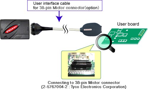
User interface cables included in the E10A-USB, HS0005KCU01H or HS0005KCU02H, are available for purchase individually. User interface cable for 38-pin Mictor connector is also available for purchase for using with HS0005KCU02H.
Note that the optional cables that come with the HS0005KCU14H is unavailable for purchase.
Product Part Number
| Product Number | Description |
|---|---|
| HS0005ECU01H | Optional cable to connect the E10A-USB emulator (HS0005KCU01H, HS0005KCU02H) to the 14-pin connector. |
| HS0005ECU02H | Optional cable to connect the E10A-USB emulator (HS0005KCU02H) to the 36-pin connector. |
| HS0005ECK01H Note1 | Optional cable to connect the E10A-USB emulator (HS0005KCU02H) to the 38-pin Mictor connector. |
Note
- The 38-pin Mictor connector is an optional cable to connect the E10A-USB emulator (HS0005KCU02H) to the 38-pin Mictor connector (2-5767004-2 : Tyco Electronics Corporation) mounted on the user system. Refer to the image of system configuration.