特性
- AI 加速器;DRP-AI
- Cortex-A55(双核或单核)
- Cortex-M33
- 3D 图形加速引擎 (Arm Mali-G31)
- 视频编解码器 (H.264)
- 摄像头接口(MIPI-CSI 或 Parallel-IF)
- 显示器接口(MIPI-DSI 或 Parallel-IF)
- USB2.0 接口 × 2、SD 接口 × 2
- CAN 接口 (CAN-FD)
- 千兆以太网接口 × 2
- 内存检错/纠错 (ECC)
- DDR4 或 DDR3L 内存接口
- BGA 封装(15x15mm,21x21mm)
- 探索瑞萨验证的 DRAM 兼容性列表

描述
RZ/V2L配备 Arm® Cortex®-A55 (1.2 GHz) CPU 和内置 AI 加速器“DRP-AI”,以提供更好的机器视觉处理性能,这是瑞萨电子的独创技术。 “DRP-AI” 由 DRP 和 AI-MAC 组成。 它还配备一个 16 位的 DDR3L/DDR4 接口,具备内置 Arm Mali-G31 的 3D 图形引擎和视频编解码器 (H.264)。
DRP-AI 的卓越功率效率使其无需采取散热措施(如散热器或冷却风扇)。 人工智能不仅可以在消费类电子产品和工业设备中经济高效实施,还可以在零售点 (POS) 终端等广泛的应用中实施。 此外,DRP-AI 还提供实时人工智能推理和图像处理功能,具有支持摄像头所必需的功能,如颜色校正和降噪。 这使得客户无需外部图像信号处理器 (ISP),即可实施基于人工智能的视觉应用。
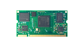
RZ/V2L 还与 RZ/G2L 封装和引脚兼容。 这使得 RZ/G2L 用户可轻松升级至 RZ/V2L,以获得额外的人工智能功能,而无需修改系统配置,从而保持低迁移成本。
产品参数
| 属性 | 值 |
|---|---|
| CPU Architecture | Arm |
| Main CPU | Cortex-A55 x 1 + Cortex-M33 x 1, Cortex-A55 x 2 + Cortex-M33 x 1 |
| Program Memory (KB) | 0 |
| RAM (KB) | 128 |
| Carrier Type | Bulk (Tray), Full Carton (Tray) |
| Supply Voltage (V) | 2.97 - 3.63 |
| I/O Ports | 123 |
| NPU | Yes |
| DRAM I/F | DDR3L-1333, DDR4-1600 (16-bit) |
| 3D GPU | Arm Mali-G31 |
| Temp. Range (°C) | Tj = -40 to +125 |
| Operating Freq (Max) (MHz) | 1200 |
| Ethernet speed | 10M/100M/1G |
| Ethernet (ch) | 2 |
| EtherCat (ch) (#) | 0 |
| USB FS (host ch/device ch) | ( 2 / 1 ), ( 2 / 2 ) |
| USB HS (host ch/device ch) | ( 2 / 1 ), ( 2 / 2 ) |
| USB SS (host ch/device ch) | ( 0 / 0 ) |
| PCI Express (generation and ch) | No |
| SCI or UART (ch) | 2 |
| SPI (ch) | 3 |
| I2C (#) | 4 |
| CAN (ch) | 0 |
| CAN-FD (ch) | 2 |
| Wireless | No |
| SDHI (ch) | 2 |
| High Resolution Output Timer | No |
| PWM Output (pin#) | 0 |
| 32-Bit Timer (ch) | 1 |
| 16-Bit Timer (ch) (#) | 8 |
| 8-Bit Timer (ch) | 0 |
| Standby operable timer | No |
| Asynchronous General Purpose Timer / Interval Timer (ch) | 0 |
| 16-Bit A/D Converter (ch) | 0 |
| 14-Bit A/D Converter (ch) | 0 |
| 12-Bit A/D Converter (ch) | 8 |
| 10-Bit A/D Converter (ch) | 0 |
| 24-Bit Sigma-Delta A/D Converter (ch) | 0 |
| 16-Bit D/A Converter (ch) | 0 |
| 12-Bit D/A Converter (ch) | 0 |
| 10-Bit D/A Converter (ch) (#) | 0 |
| 8-Bit D/A Converter (ch) | 0 |
| Capacitive Touch Sensing Unit (ch) | 0 |
| Graphics LCD Controller | No |
| MIPI Interfaces (DSI) (ch) | 1 |
| MIPI Interfaces (CSI) (ch) | 1 |
| Image Codec | H.264 enc/dec |
| Segment LCD Controller | No |
| Security & Encryption | AES, RSA, ECC, SHA-1, SHA-224, SHA-256, GHASH, TRNG, No |
应用方框图
 | 基于 LiDAR 的 SLAM 视觉建图系统 采用 LiDAR‑SLAM 视觉建图技术,为自主机器人提供稳健的环境感知与导航能力。 |
 | 智能视觉 AI 摄像头模组 AI 摄像头模块为智能应用提供各种检测功能。 |
 | 扫地机器人 这款智能扫地机器人具有环境映射、防跌落、障碍物检测、自动充电、应用程序控制等功能。 |
 | 电池供电摄像头,拥有人工智能物体检测和运动感应功能 电池供电人工智能摄像头,具有高效的运动检测、快速启动和低功耗物体分类功能。 |
 | 智能旅行箱 AI 驱动的智能旅行箱,具有物体检测和免提便利性。 |
 | 高级 HMI 和边缘 AI 应用的单板计算机 紧凑型 SBC 通过双核 MPU、DRP-AI、Wi-Fi、蓝牙 LE 和 NFC 连接支持 HMI 和边缘 AI。 |
 | 条形码扫描仪系统 支持一维/二维条形码及 NFC 的工业条形码扫描仪,具备边缘智能与灵活连接能力。 |
 | 具备 AI 加速器的 HMI SoM 可扩展的 AI 赋能 SMARC SoM,面向高性能工业 HMI |
 | 视频 IP 电话 视频 IP 电话设计,具有 Hi-Fi 高保真音频、降噪、触控显示屏和多功能连接功能。 |
其他应用
- 家电
- 摄像头应用
完成您的设计
寻找相关的产品,完善您的设计
Renesas Boards & Kits
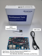
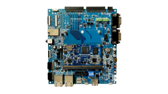
RZ/V2L 评估板套件
该评估板套件适用于评估 RZ/V2L。 RZ/V2L 评估板套件由模块板 (SOM) 和扩展板组成。 此外,产品附带 MIPI 摄像头模块 (MIPI CSI)。 扩展板通常适用于按照 SMARC v2.1 标准制备的 RZ/G2L,RZ/G2LC,RZ/G2UL,RZ/V2L模块 (SOM)。 基于这种适用性,在使用这些设备时,您可以体验到无缝且灵活的评估。
远程测试该板卡
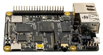
单板计算机 - 安富利 RZBoard V2L 电路板
安富利 RZBoard V2L 是一款高能效视觉 AI 加速开发板,针对人工智能(AI)/机器学习(ML)应用进行了优化。 其 Raspberry Pi 单板计算机外形紧凑,具有一组多功能扩展接口,以便使用 HDMI 或 MIPI 显示器、摄像头和 HAT/shield 附加板等硬件配件,为瑞萨电子 RZ/V2L 多核处理器系列的软件开发和评估提供了理想的平台。
远程测试该板卡
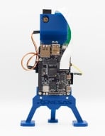
追踪摄像机演示套件
该款追踪摄像机(Trail Camera)演示套件展示了 RZ/V2L SoC 中用于人工智能(DRP-AI)子系统的动态可重构处理器的各种功能,而且该动态可重构处理器还可以快速启动 Linux(<1.6s)。 该款追踪摄像机具有复杂的系统,使用了 RZ/V2L 的所有主要子系统。 片上 Arm® Cortex-M33®(CM33)MCU 甚至在安装 Linux 之前就已用于捕获图像,并使用 DRP-AI 神经处理单元(NPU)处理图像,以快速识别复杂场景中的对象。 在命令行应用程序显示记录日志文件的同时,还能使用显示器直观地显示已识别的对象,这为产品增加了许多可扩展的功能。... 阅读详情
远程测试该板卡
Partner Boards & Kits
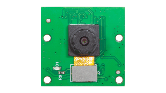
1.3M Pixels MIPI Output Camera Module KBCR-S08MM
AIC-R Camera Module
Arducam Camera Modules for AI MPU RZ/V2L
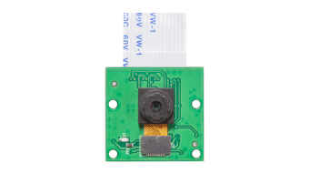
Arducam Camera Solution for AVNET RZ/V2L
DRAM & Flash Memory Solutions
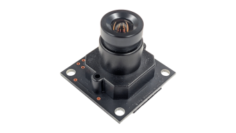
Intelligent Camera Standard Series 1.2MP Model KBCR-iC41MG
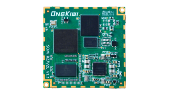
OneKiwi RZV2L System on Module (SoM)
REGULUS RZ/V2L & RZ/G2L SMARC System on Module (SoM)
RZ/V2L Arm Cortex-A55 Dual Core & Cortex-M33 Industrial SoM Computer Equipped with AI Accelerator
RZ/V2L OPTIMA System on Module (SoM)
RZ/V2L OPTIMA System on Module (SoM) Evaluation Kit
RZ/V2L OSM System on Module (SoM)
RZ/V2L Single Board Computer (SBC)
RZ/V2L SMARC 2.1 Compliant System on Module (SoM)
RZ/V2L SMARC System on Module (SoM)
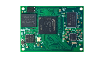
RZ/V2L System on Module (SoM)
RZ/V2L VERSA System on Module (SoM)
RZ/V2L VERSA System on Module (SoM) Evaluation Kit
TRIA SM2S-V2L
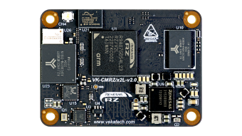
VK-CM-RZ/V2L
VK-CMx2L
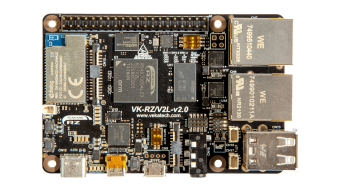
VK-RZ/V2L
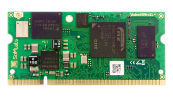
XENO+ Vision ML System on Module (SoM)
筛选
软件与工具
按类型筛选
按供应商筛选
样例程序
按应用筛选
按功能筛选
按编译器筛选
按 IDE 筛选
模拟模型
Partner Solutions
- 软件包英语This is an AI model conversion tool (DRP-AI Translator) for DRP-AI equipped products. This product is also used as an internal tool for DRP-AI TVM (required when installing DRP-AI TVM).
- 软件包英语We provide an AI model conversion tool (DRP-AI TVM) for DRP-AI-equipped products. When using this product, please check the contents of the linked README.md first.
- 软件包英语A generic software package for providing consistent experience across select reference products featuring RZ SoCs to be used in PoCs and product development, thereby streamlining and focusing on end application development while reducing BSP efforts.
- 软件包中文RZ FSP 是一款增强型软件包,旨在为基于瑞萨电子 RZ 系列 Arm 微处理器的嵌入式系统设计提供用户友好、可扩展的高质量软件。
- 软件包英语This product provides the HTML5 (Chromium) Package as a GUI framework for RZ/G3E, RZ/G2L, RZ/G2LC, and RZ/V2L.
- 软件包英语HTML5 (Gecko) package for RZ/G. This package is used in combination with the Linux package provided for the device.
- 软件包英语Security package for RZ MPUs. This package is used in combination with the Linux package provided for each device.
- 软件包英语A web‑based smart I/O power controller that simplifies relay management with flexible, intuitive software.
- 软件包中文一款用于开发多操作系统解决方案的软件包,由 FSP 和 OpenAMP 组成,前者是用于 Cortex-M 或 Cortex-R 内核 MPU 的软件包,后者是用于处理器间通信框架的标准化 API。
- 软件包英语The AI SDK enables easy and rapid development of AI applications using Renesas' RZ/V series evaluation kits. Additionally, it offers a range of AI applications free of charge.
- 软件包英语Linux packages for RZ/V2L, RZ/V2M, and RZ/V2MA MPUs. Functions of these products have been verified and regular maintenance is also provided.
- 软件包英语AI Software Development Kit (AI SDK) is an AI application development environment for the RZ/V2L Evaluation Board Kit.
- 软件包英语This product provides the software and documentation for DRP-AI embedded within RZ/V2L.
- 软件包英语This product provides the ISP Support Package for RZ/V2L. Please read the included release note first when you use the package.
- 软件包英语This product provides OpenCV Accelerator Support Package for RZ/V2L.
No Results Found.
确保所有关键词拼写正确。
尝试使用更少、不同或更宽泛的词语来改变搜索结果。
如果您使用了筛选器,请考虑取消选择某些筛选器选项以扩大搜索结果。
- 搜索我们丰富的知识库,帮助您解答常见问题
- 前往支持论坛,获取瑞萨电子技术专家和社群的帮助
- 软件包英语This is an AI model conversion tool (DRP-AI Translator) for DRP-AI equipped products. This product is also used as an internal tool for DRP-AI TVM (required when installing DRP-AI TVM).
- 软件包英语We provide an AI model conversion tool (DRP-AI TVM) for DRP-AI-equipped products. When using this product, please check the contents of the linked README.md first.
- 软件包英语A generic software package for providing consistent experience across select reference products featuring RZ SoCs to be used in PoCs and product development, thereby streamlining and focusing on end application development while reducing BSP efforts.
- 软件包中文RZ FSP 是一款增强型软件包,旨在为基于瑞萨电子 RZ 系列 Arm 微处理器的嵌入式系统设计提供用户友好、可扩展的高质量软件。
- 软件包英语This product provides the HTML5 (Chromium) Package as a GUI framework for RZ/G3E, RZ/G2L, RZ/G2LC, and RZ/V2L.查看更多 (47)
软件与工具 (47)
- 示例代码英语Demonstrates how to write code using various unified Renesas RZ Flexible Software Package (FSP) v4.x.x modules supported by the RZV2L-EVK. The unified RZ FSP consolidates all previous family‑specific FSPs into a single package and provides an optimized, easy‑to‑use, scalable, high‑quality software solution for embedded system design.
样例程序 (2)
- 模型 - IBIS英语
- 模型 - BSDL英语
模拟模型 (2)
 Development Tool中文Supporting Arm® and RX microcontrollers, the SEGGER J-Link series is an industry-standard debugger for software development. High-speed programming algorithms reduce binary transfer time and accelerate development cycles. Broad compatibility supports Renesas e² studio, major IDEs, and RZ, RA, and RX devices. Advanced analysis with Ozone and ...提供方: EmbiTeK Co., Ltd.
- Development Tool中文Provides universal device programming systems combining algorithms, process-control software, and socket modules for Renesas microcontroller production. Enables high-volume programming across the RA, RX, RL78, RH850, RZ, R8C, V850, M16C, H8, H8SX, H8S, SH, 78K and Synergy families using 9th- and 10th-generation universal site technology. Supports new socket ...提供方: BPM Microsystems
- Development Tool中文All-in-one testing tool for C and C++ developed by Parasoft that supports static analysis, unit testing, coverage measurement, and runtime memory error detection. Supports coding enforcement based on standards such as MISRA, AUTOSAR, CERT, and CWE, and enables automatic coverage collection during unit testing and application execution. Includes ...
- Development Tool中文Provides tools for developing real‑time, safety‑ and security‑critical embedded software by combining static analysis, unit testing, code coverage, requirements traceability, and compliance reporting in a unified workflow. Supports a TÜV SÜD‑certified GoogleTest‑based unit testing solution and integrates with modern development toolchains and continuous integration and continuous ...提供方: PARASOFT
- HMI中文High-performance, scalable and hardware-independent HMI software toolchain for embedded systems. Enables development of customizable 2D and 3D graphical user interfaces with a designer-centric workflow, WYSIWYG editor, no-coding methodology and AI-assisted Smart Importer. Integrated state machine and automated workflows accelerate development. Scales efficiently from low-end ...提供方: Candera GmbH查看更多 (72)
