
概览
描述
RL78/G23-64p 快速原型开发板采用 RL78/G23 微控制器,是各种原型开发的理想选择。 它通过示例代码支持音频播放、基于 LoRa 和 LoRaWAN 的无线通信等功能。 内置的仿真器电路相当于 E2 仿真器 Lite,无需额外工具即可进行编程和调试。 此外,它还具有 Arduino Uno 和 Grove 接口,可连接所有微控制器引脚,并且具有很高的可扩展性。 瑞萨电子还提供了一个 Arduino 库,支持在 Arduino IDE 里创建各种程序 (sketch)。
还提供 128 引脚开发板:RL78/G23-128p 快速原型开发板
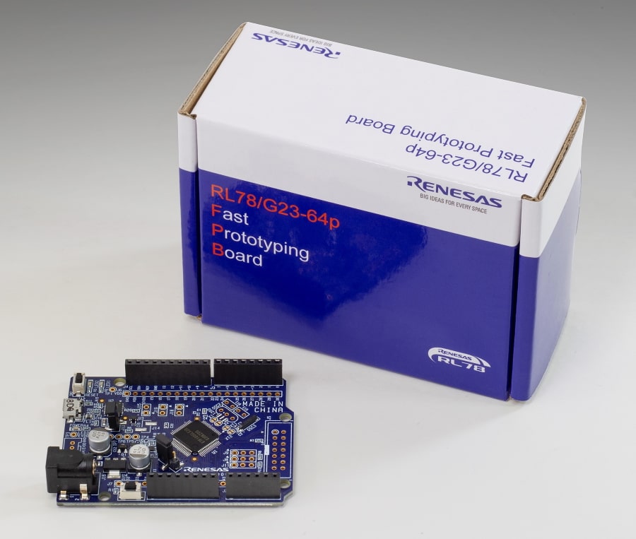
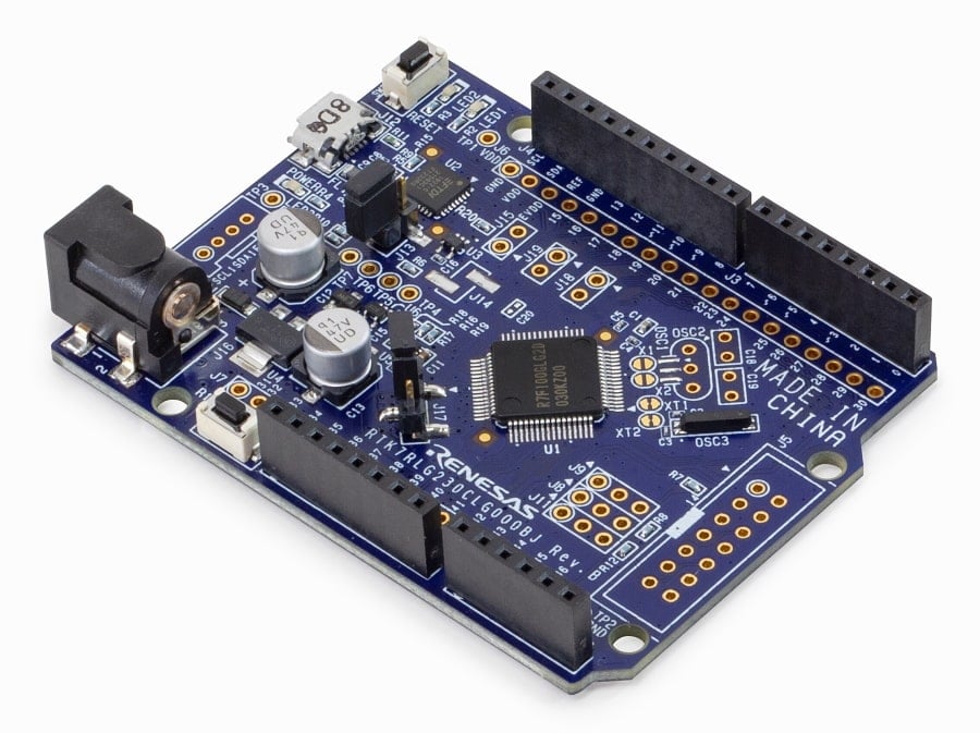
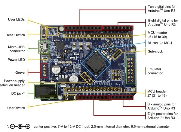
特性
- 配备 RL78/G23 16 位微控制器(R7F100GLG2DFB)
- 32MHz,RL78-S3 内核
- ROM:128KB,RAM:16KB,Data Flash 8KB
- 64 引脚 LFQFP,10mm x 10mm x 1.7mm,0.5mm 间距
- 使用 USB 线连接到电脑,即可通过 COM 端口通信编写/调试程序
- 可以连接微控制器的所有引脚
- 标配 Arduino Uno 接口
- 可提供 Arduino 库
- 支持各种 RL78 软件和工具
应用
文档
|
|
|
|
|---|---|---|
| 类型 | 文档标题 | 日期 |
| 手册 - 开发工具 | PDF 1.54 MB 日本語 | |
| 快速入门指南 | PDF 499 KB | |
| 原理图 | PDF 228 KB | |
| 其他 | PDF 168 KB | |
| 应用说明 |
PDF
1.86 MB
日本語
A system is constructed using the RL78/G23-64p Fast Prototyping Board, the BME280 (temperature, humidity, and barometric pressure sensor), and an LCD module. The Arduino IDE and Arduino libraries are used to display the sensor data on the LCD. In this sample, the temperature (°C), humidity (%), and pressure (hPa) obtained from the BME280 are shown on the LCD module.
|
|
| 应用说明 |
PDF
1.91 MB
日本語
AI 生成的摘要:
The RL78/G23 hardware design guide details essential hardware design considerations including typical circuit schematics, power supply circuits, oscillator circuits, I/O port recommendations, A/D converter notes, and on-chip debug circuits. It emphasizes proper component selection and placement, such as bypass capacitors with good frequency characteristics, and wiring patterns for power supply pins to ensure stable operation. The guide also covers power supply timing requirements, reset pin usage, and external component recommendations to optimize device performance and reliability. It includes a minimum external components list and cautions on unused pin connections and package-specific soldering instructions.
|
|
| 应用说明 |
PDF
286 KB
The Combination of Private LoRa and LoRaWAN Stack is a sample software that can switch the LoRaWAN and the Private LoRa wireless communications dynamically. This document describes the specification and usage of the sample software.
|
|
| 应用说明 |
PDF
579 KB
The LoRaWAN stack supports LoRaWAN interface which implements LoRaWAN protocol (Class A/B/C) specified in the specification version 1.0.4 and 1.0.3 which encompasses version 1.0.2. This document describes the API references and other information to use the LoRaWAN stack.
|
|
| 应用说明 |
PDF
490 KB
The LoRaWAN stack supports LoRaWAN interface which implements LoRaWAN protocol (Class A/B/C) specified in the specification version 1.0.4 and 1.0.3 which encompasses version 1.0.2. This document describes a sample software to control the LoRaWAN stack by AT command sets.
|
|
| 应用说明 |
PDF
482 KB
The Private LoRa stack supports a custom protocol for the LoRa-based wireless communication, which can be mainly used for the peer-to-peer and star network. This document describes the API references and other information to use the Private LoRa stack.
|
|
| 应用说明 |
PDF
493 KB
The Private LoRa stack supports a custom protocol for the LoRa-based wireless communication, which can be mainly used for the peer-to-peer and star network. This document describes a sample software to control the Private LoRa stack by AT command sets.
|
|
| 应用说明 |
PDF
651 KB
The LoRaWAN Sensor Demo package includes sample software that introduces how to visualize sensor data transmitted by a sensor node to Cloud (AWS/Azure) via LoRaWAN networks. This document describes the specification and usage of the sample software.
|
|
| 应用说明 |
PDF
2.01 MB
This LoRa-based wireles softwar package includes the sample software and evaluation tools to develop the LoRa and LoRaWAN based applications.This document describes the information on the contents of this package and how to setup the hardware and software.
|
|
| 应用说明 |
PDF
411 KB
The Radio Driver supports basic wireless communictions such as transmit and receive frames with LoRa-based modulation and (G)FSK modulation. This document is an API reference guide for the Radio Driver and MCU timer driver.
|
|
| 应用说明 |
PDF
430 KB
The support functions for regional radio regulations can be used for the Radio Driver to comply with the regional radio regulations. This document describes the support functions and how to configure each support function.
|
|
| 应用说明 |
PDF
426 KB
The Radio Evaluation Program can be used when to evaluate the characteristics of the board utilizing the LoRa-based transceiver. This document describes the specification and usage of the Radio Evaluation Program.
|
|
| 应用说明 |
PDF
1.15 MB
The RL78 Smart Configurator can automatically generate the driver programs to configure the peripherals, pins, interrupts, and clocks. This document describes the information on how to use the Smart Configurator for LoRa-based wireless software.
|
|
| 手册 - 软件 | PDF 370 KB | |
| 手册 - 软件 | PDF 1.86 MB | |
| 应用说明 |
PDF
618 KB
日本語
AI 生成的摘要:
The overcurrent protection function uses the ELCL to detect abnormal current flow in converters and stops PWM output to prevent damage. It monitors current via a comparator connected to a measurement resistor and controls PWM output accordingly. The system includes a reactivation switch to resume operation once the overcurrent condition clears, while disabling inputs during ongoing faults. The document details system configuration, timing charts, hardware and software setup, operation conditions, and sample code for RL78/G23 microcontrollers.
|
|
| 应用说明 | PDF 1.12 MB 日本語 | |
| 应用说明 | PDF 1022 KB 日本語 | |
| 应用说明 |
PDF
587 KB
日本語
AI 生成的摘要:
LED burst dimming control uses the logic and event link controller (ELCL) to finely adjust LED brightness by combining two PWM signals with different frequencies. A high-frequency PWM (over 100 kHz) controls current switching, while lower-frequency PWM (~1 kHz) manages overall light intensity without flicker. This method enables precise dimming for LED indicators and lighting. The system configures multiple PWM outputs and uses logical AND operations to generate burst dimming signals for two LEDs simultaneously. The document also provides hardware and software setup details, operation conditions, and sample code for implementation on the RL78/G23 microcontroller.
|
|
| 应用说明 | PDF 1.17 MB 日本語 | |
| 应用说明 |
PDF
1.31 MB
日本語
AI 生成的摘要:
Control EEPROM devices on an IIC bus using the simplified IIC function of the Serial Array Unit (SAU) in interrupt-driven mode. The document details read/write operations, supports EEPROM sizes from 2 to 512 kbits (default 16 kbits R1EX24016A), and manages bus release after resets. It explains peripheral functions, IIC communication timing, and provides comprehensive software flowcharts and sample code for implementation.
|
|
| 应用说明 |
PDF
2.43 MB
日本語
AI 生成的摘要:
The RL78/G23-64p Fast Prototyping Board controls a line trace car using Arduino IDE. The system integrates a motor driver (DRV8835), photo reflector (NJG5901AR), and DC motors to follow a black line on an oval course. The photo reflector detects black and white surfaces by measuring reflected infrared light, enabling the microcontroller to generate PWM signals that control motor speed and direction. The motor driver uses two PWM signals per motor to manage forward and reverse rotation, with the sample program configured to move forward via reverse motor control. Power supply switches from PC during development to a mobile battery for operation.
|
|
| 应用说明 |
PDF
478 KB
日本語
AI 生成的摘要:
UART communication with hardware flow control manages RTS and CTS signals to ensure reliable data transmission and reception. RTS signals indicate receiver availability by toggling between high and low levels during data reception, while CTS signals control transmission by pausing or resuming data transfer based on the opposing device's readiness. The document details pin configurations, timing charts for transmission and reception, and interrupt-driven control mechanisms to implement this flow control effectively.
|
|
| PCB 设计文件 | ZIP 3.15 MB | |
| 应用说明 |
PDF
2.32 MB
日本語
AI 生成的摘要:
The system uses the RL78/G23-64p Fast Prototyping Board, a three-axis accelerometer (GY 291 ADXL345), and an LCD module (EMB-LCD-1602B) to count steps. The accelerometer measures acceleration in X, Y, and Z axes via I2C communication. The step count displays on the LCD, with LED indicators showing counting status and user interaction. The system operates through Arduino IDE, using sample code with step-counting algorithms and peripheral control. The document details hardware setup, software structure, and operation flow for implementing a pedometer using the RL78/G23 platform.
|
|
| 应用说明 |
PDF
1.37 MB
日本語
AI 生成的摘要:
Audio playback of ADPCM data stored in NOR FLASH is achieved using the I2S master function on the RL78/G23 microcontroller. The system integrates NOR FLASH control via the Serial NOR Flash Memory Control Module Software Integration System (SIS) and uses M3S-S2-Tiny middleware for ADPCM encoding and decoding. The I2S communication supports PCM format with sampling frequencies of 8 kHz to 22.05 kHz and 16-bit data size. The document details hardware and software configurations, including pin usage, commands for writing and reading NOR FLASH, error handling, and flow charts for key functions. It also covers audio playback methods, middleware integration, and sample code for implementation.
|
|
| 应用说明 |
PDF
391 KB
日本語
AI 生成的摘要:
The A/D test function verifies the normal operation of the A/D converter by performing conversions at three reference voltages: internal 0 V, VDD, and an internal reference voltage of 1.48 V. The process uses software-triggered, one-shot conversions and checks if the results fall within allowable ranges. If all tests pass, LED1 lights steadily; if any test fails, LED1 blinks. The procedure includes initializing the A/D converter, switching test voltages, starting conversion, entering HALT mode to await completion, and evaluating results. The document details peripheral usage, register settings, and flowcharts for implementing this safety function on the RL78/G23.
|
|
| 应用说明 |
PDF
452 KB
日本語
AI 生成的摘要:
The document explains how to implement a hardware-based chattering prevention circuit using the RL78/G23 microcontroller's ELCL (Event Link Controller). It replaces external parts and software debounce methods by using ELCL and TAU0 timer functions to filter switch contact noise caused by mechanical chattering. The system controls input signals from mechanical switches, ensuring reliable single-press detection by delaying output signals until chattering subsides. Detailed specifications, hardware configuration, software structure, timing charts, and operation conditions are provided. The document also includes sample code, component settings, and test conditions for effective implementation.
|
|
| 应用说明 |
PDF
268 KB
日本語
AI 生成的摘要:
The document explains how to implement a watchdog timer function using the SNOOZE mode sequencer (SMS) of the RL78/G23 microcontroller. The SMS operates independently from the CPU by running a counter that triggers an interrupt if it overflows before being cleared by the CPU. This mechanism allows the CPU to detect faults and respond, such as turning on an LED. The document details the peripheral functions involved, operation flow, hardware configuration, software setup, and sample code. It also specifies the operating conditions and development environments used for testing.
|
|
| 应用说明 |
PDF
472 KB
日本語
AI 生成的摘要:
The document explains how to implement a button press detection system that distinguishes between long and short presses using the SNOOZE mode sequencer on the RL78/G23 microcontroller. It details the process of detecting button press duration during STOP mode, triggering interrupts, and waking the CPU upon a long press. The system uses INTP0 interrupt and ELCL to start SMS processing, which judges the press duration and issues a wakeup request if the press is long. The document includes hardware configuration, software structure, flowcharts, and sample code to support development and customization.
|
|
| 应用说明 |
PDF
456 KB
日本語
AI 生成的摘要:
The document explains how to use the fixed-cycle interrupt and alarm interrupt functions of the RL78/G23 realtime clock. It details the setup to invert output port signals and display time on an LCD, and to trigger an alarm interrupt five seconds after a preset time. The RTC operates continuously, showing time even during resets. It covers hardware configurations, software initialization, interrupt handling, and communication with an LCD via I2C. The sample code runs on the RL78/G23 MCU and includes LED control synchronized with RTC interrupts. Operation conditions and peripheral functions are specified for reliable implementation.
|
|
| 应用说明 |
PDF
3.85 MB
日本語
AI 生成的摘要:
The RL78/G23-64p Fast Prototyping Board integrates with a GNSS module and micro-SD card module to capture and log satellite-based location and time data. Using Arduino IDE, the system collects GNSS data in NMEA format via UART, processes it into GIS-compatible formats, and stores it on a micro-SD card. The system features LED indicators for data reception and logging status, and supports displaying logged data on open-source GIS software. The GNSS module supports multiple satellite systems including GPS, Beidou, and Galileo, while the micro-SD card module uses SPI communication with voltage level conversion for compatibility.
|
|
| 应用说明 |
PDF
2.29 MB
日本語
AI 生成的摘要:
The document explains how to use the RL78/G23-64p Fast Prototyping Board with Arduino IDE to control a piezoelectric sounder and an I2C LCD display. It demonstrates programming a countdown timer that shows remaining time on the LCD and plays a melody via the sounder when the timer reaches zero. The system uses square wave frequencies to generate musical notes and communicates with the LCD through I2C using minimal pins. It also details the hardware and software environment required for operation, including board specifications, sounder model, LCD module, and Arduino IDE version.
|
|
| 应用说明 |
PDF
326 KB
日本語
AI 生成的摘要:
Remote control signals in AEHA format, including header and 48-bit data, are received using a remote control signal receiver (REMC) and processed in STOP mode to conserve power. LEDs light up corresponding to the received remote control channel. If no signal is detected for 10 seconds, the MCU enters STOP mode and wakes upon signal detection using a low-speed peripheral clock. Frequency correction for the low-speed oscillator is performed at startup to ensure accurate timing. The document details peripheral usage, signal timing, LED control, and state transitions between normal and STOP modes.
|
|
| 应用说明 |
PDF
339 KB
日本語
AI 生成的摘要:
The document explains how to receive NEC-format remote control signals using a remote control signal receiver (REMC) and manage power efficiently by transitioning the MCU to STOP mode after 10 seconds of inactivity. It details how LEDs correspond to received remote control signals, the timing and data format of NEC signals, and the use of low-speed peripheral clocks for signal processing during STOP mode. The document also covers frequency correction for the low-speed oscillator and provides hardware and software configuration guidance, including interrupt handling and state transitions between normal and STOP modes.
|
|
| 应用说明 |
PDF
684 KB
日本語
AI 生成的摘要:
The method dynamically controls a four-digit 7-segment LED indicator using the SNOOZE mode sequencer (SMS) on the RL78/G23 MCU. The CPU reads time from the RTC, converts it into segment data, and stores it in memory. The SMS then reads this data every 2 ms and drives the LED segments and digit selection signals without CPU intervention, enabling low power consumption. The system uses a cathode-common 7-segment LED directly controlled via ports P10-P17 for segments and P70-P73 for digit selection. Key peripherals include a 32-bit interval timer for SMS activation and the RTC for timekeeping.
|
|
| 应用说明 |
PDF
378 KB
日本語
AI 生成的摘要:
The SNOOZE mode sequencer (SMS) of the RL78/G23 automatically controls SPI master communication by managing slave select pins and data transfer. Triggered by an external interrupt, the SMS selects one of three slave devices, reads transmit data from RAM, performs data transmission and reception via the CSI00 interface, and stores received data back into RAM. It supports send, receive, and send/receive modes, automatically handling transmission counts and data addresses. Upon completion, the SMS clears the slave selection and issues an interrupt request to notify the CPU.
|
|
| 应用说明 |
PDF
589 KB
日本語
AI 生成的摘要:
The document explains how to detect fires by sensing smoke using a system based on the RL78/G23 microcontroller. It utilizes the SNOOZE mode sequencer (SMS) to control the smoke sensor, measure sensor output via an A/D converter, and judge the measurement result while the CPU clock is stopped, achieving low power consumption. The system uses a 32-bit interval timer to trigger periodic sensor measurements. If the measured value exceeds a threshold, the CPU wakes up to respond. The document details hardware configuration, software structure, SMS settings, and sample code for implementing smoke detection with low power operation.
|
|
| 应用说明 |
PDF
496 KB
日本語
AI 生成的摘要:
LED brightness control uses the SNOOZE mode sequencer (SMS) triggered by a 32-bit interval timer interrupt to gradually dim LEDs from 100% to 0%. PWM output from the timer array unit (TAU) manages LED brightness by adjusting duty cycles stored in RAM. This method reduces power consumption by operating in HALT mode, where the CPU clock stops and SMS handles PWM changes autonomously. The system configuration includes the interval timer, SMS, TAU, and CPU, with flowcharts illustrating the process from initialization to LED dimming completion.
|
|
| 应用说明 |
PDF
312 KB
日本語
AI 生成的摘要:
The RL78/G23 microcomputer uses the SNOOZE mode sequencer (SMS) to monitor the execution of periodic processing by running a timer counter that the CPU must clear regularly. If the CPU fails to clear the counter within a set time, the counter overflows and triggers an interrupt, signaling missed periodic tasks. The SMS timer function supports three channels, each configurable for enable/disable status, compare values to set overflow timing, and counter clearing. External interrupts detect switch inputs and trigger SMS activation. Interrupt requests (INTP1, INTP2, INTP4) handle overflow events, allowing the CPU to respond accordingly. Channels 2 and 3 are optional and require additional interrupt processing if enabled.
|
|
| 应用说明 |
PDF
766 KB
日本語
AI 生成的摘要:
Calculates the moving average of an analog input voltage using the SNOOZE mode sequencer (SMS) while the CPU clock is stopped, enabling lower power consumption. A 32-bit interval timer triggers SMS to perform A/D conversion and moving average calculation, storing results in RAM. Pressing SW1 triggers an interrupt to wake the CPU, which then transmits the stored average via UART2. The document details system configuration, flowcharts, hardware setup, software structure, and sample code for implementing this low-power moving average calculation on the RL78/G23.
|
|
| 应用说明 |
PDF
610 KB
日本語
AI 生成的摘要:
The document explains how to implement a power supply monitoring system using the SNOOZE mode sequencer (SMS) in STOP mode to reduce power consumption. It details measuring power supply voltage via the ADC, setting measurement intervals with an interval timer (TML32), and triggering CPU wake-up when voltage drops below a threshold. The SMS handles ADC conversion and voltage judgment autonomously, generating an interrupt (INTSMSE) to activate the CPU only when necessary. The document includes hardware configuration, software structure, flowcharts, and sample code to facilitate implementation and evaluation on the RL78/G23 microcontroller.
|
|
| 应用说明 |
PDF
607 KB
日本語
AI 生成的摘要:
The document explains a fire detection system using smoke sensors controlled by the SNOOZE mode sequencer (SMS) on the RL78/G23 microcontroller. It achieves low power consumption by stopping the CPU clock while controlling sensors, measuring outputs via the ADC, and judging results. When sensor measurements exceed thresholds, the CPU wakes to respond. The system uses a 32-bit interval timer to trigger sensor measurements periodically. The document details hardware configuration, software structure, SMS settings, and sample code for implementing smoke-based fire detection with efficient power management.
|
|
| 应用说明 |
PDF
364 KB
日本語
AI 生成的摘要:
The document explains how to implement handshake-based SPI master transmission and reception using the serial array unit (SAU) with CSI communication. It details the use of chip select (CS) signals to select slave devices and BUSY signals for handshake synchronization, ensuring the slave is ready before communication starts. Communication occurs in 1 ms slots with commands for status check, transmit, receive, and transmit/receive operations. The document also covers hardware configurations, peripheral functions, timing charts, and software flowcharts to support reliable SPI communication.
|
|
| 应用说明 |
PDF
168 KB
日本語
AI 生成的摘要:
The RL78/G23 A/D converter in scan mode converts analog signals from pins ANI2, ANI3, ANI4, and ANI5 into 12-bit digital values stored in on-chip RAM. It operates with software-triggered sequential conversion and uses VDD and VSS as reference voltages. The document details initial register settings, conversion timing, and interrupt handling for efficient data acquisition. Operation is confirmed on the RL78/G23 MCU with a 32 MHz clock and 5.0 V supply. Development environments supported include CS+, e2studio, and IAR Embedded Workbench. The document also provides hardware configuration, software flowcharts, and sample code for implementation.
|
|
| 应用说明 |
PDF
461 KB
日本語
AI 生成的摘要:
The flash memory CRC operation function performs high-speed CRC on code flash memory and general-purpose CRC on on-chip RAM to verify data integrity. It compares CRC results with pre-generated values, lighting LEDs upon matches. The high-speed CRC targets flash memory addresses 00000H to 0FFFBH, while the general-purpose CRC operates on RAM data that can be switched via input. The operation sequence includes initialization, CRC processing, comparison, and LED indication, with repeated cycles triggered by interrupts. The document details hardware setup, software configuration, and sample code for implementing these safety functions.
|
|
| 应用说明 |
PDF
181 KB
日本語
AI 生成的摘要:
The RL78/G23 uses two comparators combined as a window comparator to monitor an analog input voltage against two reference voltages: a lower internal reference and a higher output from a D/A converter. The VCOUT0 pin outputs a HIGH signal when the input voltage lies between these thresholds and LOW otherwise. The system employs digital filtering and interrupt-driven polarity changes on the VCOUT0 output. The document details initialization steps for I/O ports, D/A converter, and comparators, including setting modes, reference voltages, filters, and interrupt configurations. It also explains how comparator interrupts adjust output polarity based on input voltage levels relative to the reference voltages.
|
|
| 应用说明 |
PDF
257 KB
日本語
AI 生成的摘要:
The RL78/G23 integrates two voltage detectors (LVD0 and LVD1) to monitor power supply voltage and manage CPU operation modes. LVD0 operates in reset mode, generating a reset signal when voltage falls below a set threshold, while LVD1 operates in interrupt mode, triggering a clock frequency change to reduce power consumption when voltage drops. The CPU clock switches between 32 MHz and 32.768 kHz based on voltage levels, indicated by LED flashing intervals. Switch inputs cycle through three LEDs, and RAM data retention depends on reset source. The document details hardware configuration, software setup, and interrupt handling for efficient voltage detection and power management.
|
|
| 应用说明 |
PDF
432 KB
日本語
AI 生成的摘要:
The 32-bit interval timer operates in 8-bit counter mode to control LED indications by monitoring compare match detection flags during timer interrupts. The timer interrupt intervals adjust dynamically based on the number of switch presses detected via an external interrupt pin. The document details peripheral functions such as the interval timer, external interrupt input, and port outputs for LED control. It explains timer and interrupt relationships, operation flow, and provides sample code and hardware configuration examples to implement and evaluate this functionality on the RL78/G23 microcontroller.
|
|
| 应用说明 |
PDF
207 KB
日本語
AI 生成的摘要:
The document explains how to use the software trigger wait mode of the RL78/G23 A/D converter to convert analog voltages from the P22/ANI2 pin into 12-bit digital values stored in internal RAM. It details initialization steps, including select mode for channel selection, one-shot conversion mode, software-triggered start, and interrupt-driven conversion completion. The CPU enters HALT mode during conversion, waking on interrupt to store results. Hardware configuration and pin usage are outlined, with operation confirmed on the RL78/G23 MCU at 32 MHz and 5 V. Development environments and compilers supported are also listed.
|
|
| 应用说明 | PDF 1.43 MB 日本語 | |
| 应用说明 |
PDF
182 KB
日本語
AI 生成的摘要:
The document explains how to control output currents on ports P60 and P61 of the RL78/G23 microcontroller to adjust LED brightness by pressing a switch. It details peripheral functions like port output and external interrupts, and outlines the initialization and operation of output current control ports and edge-detecting interrupts. The output current shifts through multiple levels (Hi-Z, 2mA, 5mA, 10mA, 15mA) with each switch press. Operation conditions, hardware setup, software configuration, and sample code are provided to support implementation and testing.
|
|
| 应用说明 |
PDF
270 KB
日本語
AI 生成的摘要:
The document explains how to switch operation states of the RL78/G23 microcontroller by pressing a button that triggers an external interrupt (INTP0). It cycles through four flash operation modes: High Speed (HS), Low Speed (LS), Low Power (LP), and back to LS, with LED indicators showing the current mode. Initial settings configure port pins for LED control, clock generation for 32 MHz operation, and interrupt handling for switch input. The document details hardware setup, software configuration, and operation confirmation conditions, including supported frequencies, voltages, and development environments.
|
|
| 应用说明 |
PDF
268 KB
日本語
AI 生成的摘要:
The document explains how to transfer A/D conversion results from multiple analog input channels to on-chip RAM using the Data Transfer Controller (DTC) and A/D converter in RL78/G23 microcontrollers. It covers hardware trigger modes, sequential conversion, and the use of the realtime clock interrupt as a trigger. Detailed peripheral functions, hardware configurations, and timing diagrams illustrate the process of storing conversion data efficiently. The document also includes software setup, flowcharts, and sample code to facilitate implementation.
|
|
| 应用说明 |
PDF
338 KB
日本語
AI 生成的摘要:
The document explains how to receive UART data during STOP mode by using the UARTA function and key interrupt on RL78/G23. It details detecting the start bit’s falling edge to exit STOP mode and initiate UART reception. The UARTA function handles 8-bit data with even parity at 9600 bps, using specific pins for transmission and reception. It also covers interrupt handling for reception, transmission, and errors, along with timer settings for timeout detection. Baud rate tolerance and error response data are specified to ensure reliable communication. The document includes hardware configuration, software flowcharts, and sample code to implement the described functionality.
|
|
| 应用说明 |
PDF
1.31 MB
日本語
AI 生成的摘要:
The document explains how to use the RL78/G23-64p Fast Prototyping Board with the Arduino Motor Shield Rev3 to control a DC motor via the Arduino IDE serial monitor. It details the hardware setup including pin assignments for motor control, and the software environment including the Arduino IDE and RL78/G23-64p FPB library. The motor shield supports speed, direction, and braking control for two motors, with sample code demonstrating control of one motor channel. The document also covers system configuration, API functions, operation procedures, and troubleshooting tips.
|
|
| 应用说明 |
PDF
1.23 MB
日本語
AI 生成的摘要:
The document explains how to use the RL78/G23-64p Fast Prototyping Board with the HS3001 humidity and temperature sensor to display sensor data on the Arduino IDE serial monitor. It details the hardware setup, including board connections and jumper settings, and software environment requirements such as Arduino IDE version and libraries. The sample code structure, API functions, and operating procedures for reading sensor data are outlined. The document also covers troubleshooting tips and provides sample code and reference materials.
|
|
| 工具新闻 - 注意事项 | PDF 108 KB 日本語 | |
| 应用说明 |
PDF
434 KB
日本語
AI 生成的摘要:
UART communication is implemented using the Serial Array Unit (SAU) on the RL78/G23 microcontroller. The UART0 channel uses TxD0 and RxD0 pins for data transmission and reception at 9600 bps with 8-bit data length, LSB first, and even parity. The system analyzes ASCII characters received from the opposite device and sends corresponding responses or error codes for parity, framing, and overrun errors. Interrupts handle reception, transmission completion, and errors with low priority settings. Timing charts illustrate the UART data transmission and reception sequences.
|
|
| 应用说明 |
PDF
503 KB
日本語
AI 生成的摘要:
The document explains how to implement handshake-based SPI slave communication using the serial array unit (SAU) with the RL78/G23 microcontroller. It details the use of the chip select (CS) signal to select slaves and the BUSY signal for handshake synchronization. Communication occurs via CSI, a clock-synchronous serial interface using SCK, SI, SO, and CS signals. Commands such as status check, receive, transmit, and transmit/receive operate in 1 ms slots. The document also covers hardware configurations, pin usage, software functions, and timing charts for effective slave communication.
|
|
| 应用说明 |
PDF
1.33 MB
日本語
AI 生成的摘要:
Firmware updates occur by dividing code flash memory into Execute and Temporary areas, enabling updates while the application runs. UART communication uses four commands—START, WRITE_BOOT1, WRITE_TEMP, and END—to manage updates. LEDs indicate command status and operation states. The Renesas Flash Driver RL78 Type01 handles flash reprogramming and boot swapping. Sample projects for 128KB and 768KB ROM sizes demonstrate firmware replacement, with LED port assignments differing accordingly. Peripheral functions include UART0 for data communication and digital outputs controlling LEDs. The document details command processing, memory operations, and sample program structure to facilitate reliable firmware updates.
|
|
| 应用说明 |
PDF
263 KB
日本語
AI 生成的摘要:
The TRNG software driver generates true random numbers on RL78 Family MCUs, specifically confirmed on the RL78/G23. It provides functions to start random number generation and retrieve 32-bit random values, handling error states like busy or success. Usage includes generating single or multiple random numbers with example function calls. The driver is not reentrant and stops the generator after data retrieval. Sample programs demonstrate integration in various development environments with RL78/G23 hardware.
|
|
| 应用说明 |
PDF
419 KB
日本語
AI 生成的摘要:
The document explains how to use the unique ID read driver for RL78/G23 microcontrollers, which reads a 16-byte unique ID and a 9-byte product name stored in the chip. It details the unique ID’s specifications and practical applications such as preventing software piracy, seeding pseudorandom number generators, managing shipped products, and enabling program branching by product name. The document also outlines the confirmed operation environment, software configuration, API functions, and sample project usage to facilitate secure and efficient product management.
|
|
| 应用说明 |
PDF
577 KB
日本語
AI 生成的摘要:
The document explains how to use the VBAT pin on the RL78/G23 microcontroller to maintain the real-time clock (RTC) operation during power loss from the main VDD supply. When powered from VDD, the RTC updates the LCD display with clock time via fixed-cycle interrupts. If power switches to VBAT, the RTC continues running but the LCD does not display the time. The voltage detector (LVD0) monitors power source changes and triggers interrupts accordingly. The VBAT pin supplies limited current (max 150 µA) and requires external diodes to prevent backflow. The document details peripheral settings, hardware configuration, and software flow for managing VBAT operation and RTC display.
|
|
| 应用说明 |
PDF
605 KB
日本語
AI 生成的摘要:
The ELCL edge detection thinning function reduces input signal edge detection frequency by enabling detection once every two input pulses, implemented via hardware to save software resources. It uses an external input signal (INPUT A) and a clock signal (CLOCK B) to produce a thinned output signal (OUTPUT C). The system masks the first detected edge and enables the second, effectively thinning the input signal. The document details hardware setup, software configuration, timing, and operation conditions for the RL78/G23 microcontroller, including sample code and testing environments.
|
|
| 应用说明 |
PDF
605 KB
日本語
AI 生成的摘要:
The document explains how to decode Manchester code using the Logic and Event Link Controller (ELCL) in the RL78/G23 microcontroller. It covers the G.E.Thomas Manchester code decoding method, detailing the hardware configuration involving ELCL, Timer Array Unit (TAU0), and Serial Array Unit (SAU0). The timing and setup of one-shot pulse output and continuous transfer modes are described to ensure accurate decoding. The first byte received is treated as invalid, with subsequent bytes considered valid data. The document also includes sample program details, hardware setup, and configuration steps for effective Manchester code decoding.
|
|
| 应用说明 |
PDF
863 KB
日本語
AI 生成的摘要:
The ELCL enables monitoring multiple input signals by linking them through OR gates and flip-flops to generate output signals and monitor registers. This allows ports without external interrupt functions to trigger interrupts via ELCL, reducing the need for external parts and software resources. The document details hardware and software configurations, timing charts, and example setups for RL78/G23, demonstrating how to use ELCL for efficient multiple parameter monitoring and interrupt generation.
|
|
| 应用说明 |
PDF
572 KB
日本語
AI 生成的摘要:
The ELCL (Event Link Controller) enables implementation of a slave select (SS) pin function for 4-wire SPI communication using the RL78/G23 microcontroller. It extends the 3-wire serial interface (CSI) by adding SS control, allowing the slave device to communicate only when SS is low. The document details hardware pin assignments, timing charts, and system configuration for SS signal control. It includes sample code, hardware setup, software structure, and operation conditions to facilitate reliable SPI slave selection and communication.
|
|
| 应用说明 |
PDF
756 KB
日本語
AI 生成的摘要:
Firmware upgrade uses external flash memory accessed via simplified SPI (CSI) communication to update code flash memory on the RL78/G23. The MCU reads upgrade data from external flash and writes it into internal code flash using the Renesas Flash Driver (RFD) RL78 Type 01. The process includes displaying firmware version on an LCD, entering self-programming mode triggered by an external interrupt, and verifying successful reprogramming before resetting the CPU. Key peripherals involved are CSI11 for SPI communication, IICA0 for LCD control via I2C, and external interrupts for user input. The document details memory configuration, self-programming requirements, and software flow for reliable firmware updates.
|
|
| 应用说明 |
PDF
638 KB
日本語
AI 生成的摘要:
The document explains how to control the HS300x humidity sensor using RL78/G23 microcontroller via I2C communication in low-power SNOOZE mode. It details dividing I2C communication into multiple steps executed sequentially by the SMS (SNOOZE mode sequencer), with the DTC (data transfer controller) updating SMS instructions. The system uses an interval timer to trigger communication, enabling efficient humidity measurement with reduced CPU load. The sensor data is processed to determine humidity levels, with example threshold comparison included. The document also covers hardware configuration, software structure, flowcharts, and sample code for implementation.
|
|
| 应用说明 |
PDF
428 KB
日本語
AI 生成的摘要:
The Timer Array Unit (TAU) measures pulse intervals by detecting valid edges on the timer input pin (TI00) and capturing the timer count value. Each measurement stores the pulse interval in on-chip RAM. The process involves initializing TAU0 channel 0 in capture mode, setting the input to detect rising edges, enabling interrupts, and repeatedly capturing pulse intervals up to eight times. After measurements, the timer stops counting and enters HALT mode. Operation confirmation uses RL78/G23 MCU with a 32 MHz clock and supports multiple development environments. The document includes hardware configuration, software setup, flowcharts, and sample code for implementing pulse interval measurement.
|
|
| 应用说明 |
PDF
415 KB
日本語
AI 生成的摘要:
The Timer Array Unit (TAU0) measures pulse intervals by detecting rising and falling edges on the TI00 input pin, capturing timer counts to calculate high-level and low-level pulse widths. Measurement results store in on-chip RAM. The process involves configuring TAU0 channel 0 for capture mode, enabling interrupts, and handling edge detection with flags to store valid pulse widths while discarding invalid measurements. The sample code operates on RL78/G23 under specified hardware and software conditions, supporting accurate pulse width measurement for embedded applications.
|
|
| 应用说明 |
PDF
403 KB
日本語
AI 生成的摘要:
Remote control signals in AEHA format, including header and 48-bit data, are received using a remote control signal receiver (REMC) with the RL78/G23 MCU. LEDs light up according to the received channel signals. If no signal is detected for 10 seconds, the MCU enters STOP mode. Upon detecting a signal in STOP mode, it switches to SNOOZE mode to resume reception processing. The document details peripheral functions, signal-to-LED mapping, timing diagrams, and software state transitions for efficient power management and signal handling.
|
|
| 应用说明 |
PDF
417 KB
日本語
AI 生成的摘要:
The document explains how to receive NEC-format remote control signals using a remote control signal receiver (REMC) and manage power efficiently by switching between normal, SNOOZE, and STOP modes. LEDs turn on corresponding to received remote control channel signals. If no signal is detected for 10 seconds, the MCU enters STOP mode. Upon signal detection in STOP mode, it transitions to SNOOZE mode to resume reception and then returns to normal operation. The document details signal timing, peripheral usage, state transitions, and sample code for implementing this functionality on the RL78/G23 microcontroller.
|
|
| 应用说明 |
PDF
522 KB
日本語
AI 生成的摘要:
The document explains how to receive RC-6 format remote control signals using a timer array unit and external interrupts. It details how LEDs respond to specific remote control codes and how the system enters STOP mode after 10 seconds of inactivity to save power. Upon receiving a signal in STOP mode, the system resumes signal reception. It covers signal timing, data structure, and the mapping of remote control commands to LED outputs, providing a comprehensive guide for implementing remote control signal reception and power management.
|
|
| 白皮书 |
PDF
410 KB
日本語
The RL78/G23’s Logic and Event Link Controller (ELCL) adds logic circuits like AND, OR, and flip-flops to the Event Link Controller, enabling peripheral event linking without CPU intervention. This allows complex combinations and new functions without external circuits or CPU load. This paper provides an overview of ELCL, its usage, and practical applications.
|
|
| 应用说明 |
PDF
921 KB
日本語
AI 生成的摘要:
The document explains how to use the RL78/G23 microcontroller as an I2C master to communicate with multiple slave devices, specifically four serial memory areas each with unique slave addresses. It details the I2C bus operation in fast mode (up to 400 kbps), including reading and writing data sequences, and managing communication status through specific registers and interrupts. The document covers initial hardware and timer settings, I2C bus control states, and provides a library of functions for data transmission, reception, polling, and stop condition generation. It also includes flowcharts and sample code to facilitate implementation.
|
|
| 应用说明 |
PDF
956 KB
日本語
AI 生成的摘要:
The document explains how to implement self-programming on the RL78/G23 microcontroller using UART communication and boot swapping. It details rewriting the boot area in flash memory by utilizing the Renesas Flash Driver RL78 Type01. The process involves receiving commands via UART to erase, write, and verify code flash memory, followed by a boot swap to activate the new program. The sample program also manages peripheral functions like UART0 for data reception and IICA0 for LCD communication, displaying program versions on an LCD and indicating flash access via LED1.
|
|
| 应用说明 |
PDF
430 KB
日本語
AI 生成的摘要:
The interval timer function of the Timer Array Unit (TAU0) inverts an LED each time a timer interrupt (INTTM00) occurs. The timer interrupt cycle changes based on the number of switch presses, cycling through intervals of 500 ms, 250 ms, 125 ms, and 62.5 ms. The setup includes initializing the TAU0 in interval timer mode, configuring the LED output port, and setting external interrupts on switch input edges. The timer counts interrupts, toggling the LED every 250 interrupts, while the switch input adjusts the timer interval dynamically.
|
|
| 应用说明 |
PDF
434 KB
日本語
AI 生成的摘要:
The document explains how to implement PWM output using the timer array unit (TAU0) channels 0 and 1 in simultaneous operation mode. It controls LED brightness by adjusting the PWM duty cycle and toggles an LED output every 500 ms. The PWM pulse cycle is set to 2 ms, with duty cycles varying from 10% to 90% in 20% increments. The program uses timer interrupts at 2 ms intervals to update the duty cycle and invert LED output, demonstrating precise PWM control for LED brightness modulation.
|
|
| 应用说明 |
PDF
645 KB
日本語
AI 生成的摘要:
UART communication operates through the UARTA serial interface using the RL78/G23 microcontroller. The system transmits ASCII characters based on received data and handles errors by sending specific error codes. UARTA0 uses pins P72 (TxDA0) and P71 (RxDA0) for transmission and reception, respectively, with settings including 8-bit data length, LSB first, even parity, and 9600 bps transfer rate. Interrupts manage reception, transmission, and errors, with the system entering a wait state until an interrupt occurs. The document details hardware configuration, software settings, flowcharts, and sample code for implementing UART communication.
|
|
| 应用说明 |
PDF
724 KB
日本語
AI 生成的摘要:
The RL78/G23 supports an I2C slave function capable of handling multiple slave addresses simultaneously. It enables access to four separate 256-byte serial memory areas, each designated by a unique slave address. The device operates in fast mode (up to 400 kbps) and uses an all-addresses matching function to identify valid slave addresses, generating interrupts accordingly. Data transfers involve sequential reading and writing to designated register addresses within the selected memory area, with address auto-increment and wrap-around. The document details hardware configurations, peripheral settings, and software flowcharts necessary to implement this multi-address I2C slave functionality.
|
|
| 应用说明 |
PDF
593 KB
日本語
AI 生成的摘要:
The frequency detection function compares the high-speed on-chip oscillator clock (HOCO) and the low-speed on-chip oscillator clock (32.768 kHz) to detect abnormal clock frequencies. It measures pulse intervals using timer array unit 0 (TAU0), with HOCO as the count clock and the low-speed oscillator as the timer input. If the frequency is normal, an LED turns off; if abnormal, the LED blinks. The count clock frequency can be dynamically changed via a switch, with LED indicators showing the current clock state. The process involves initializing TAU0, measuring pulse intervals, entering HALT mode, and handling interrupts to verify frequency status or switch clock settings.
|
|
| 应用说明 |
PDF
604 KB
日本語
AI 生成的摘要:
The document explains how to correct the high-speed on-chip oscillator (HOCO) frequency in RL78/G23 microcontrollers by adjusting the HIOTRM register. It uses either a subsystem clock or an external input signal to detect frequency errors and calibrate the HOCO to approximately 32 MHz within ±0.1%. The calibration involves measuring pulse intervals with a 32-bit interval timer, and correction results can be verified via a 2 MHz output on the PCLBUZ0 pin. The document details peripheral settings, initialization procedures, and two calibration methods to ensure precise HOCO frequency adjustment.
|
|
| 应用说明 |
PDF
446 KB
日本語
AI 生成的摘要:
The document explains how to correct the oscillation frequency of the low-speed on-chip oscillator (LOCO) in RL78/G23 microcontrollers by using the low-speed on-chip oscillator trimming register (LIOTRM). It detects frequency errors by measuring the LOCO period with a 32-bit interval timer driven by a high-speed on-chip oscillator (HOCO). Calibration adjusts LIOTRM to bring the LOCO frequency close to 32.768 kHz within a ±1.3% range. Two calibration methods are detailed, involving peripheral settings such as external interrupts, timers, and capture modes. The process includes measuring pulse intervals multiple times to enhance accuracy and adjusting the trimming register accordingly. The document also provides sample code and hardware configuration examples.
|
|
| 应用说明 | PDF 445 KB 日本語 | |
| 白皮书 |
PDF
1.13 MB
日本語
, English
2021 年 4 月推出的 RL78/G23 微控制器(MCU)比以前的 RL78 产品有了大幅提升,能够满足当今不断发展的要求。RL78/G23 MCU 专为物联网时代而设计,结合了超低功耗、先进的智能功能和简化的开发工具,可满足基础型应用的各种需求。本白皮书探讨了 RL78/G23 系列如何成功应对种种苛刻挑战。
|
|
91 项目
|
||
设计和开发
软件与工具
软件与工具
| Software title
|
Software type
|
公司
|
|---|---|---|
| E2 emulator Lite [RTE0T0002LKCE00000R] On-chip debugging emulator. Also available as a flash memory programmer. [Support MCU/MPU: RA, RE, RL78, RX, RISC-V MCU]
|
Emulator | 瑞萨电子 |
| E2 emulator [RTE0T00020KCE00000R] On-chip debugging emulator. Also available as a flash memory programmer. [Support MCU/MPU: RA, RE, RH850, R-Car D1, RL78, RX, RISC-V MCU]
|
Emulator | 瑞萨电子 |
| C Compiler Package for RL78 Family [CC-RL] C Compiler Package for RL78 Family [IDE: CS+, e² studio]
|
Compiler/Assembler | 瑞萨电子 |
| CS+ 瑞萨电子集成开发环境(IDE)[支持 MCU/MPU:RH850、V850、RX、RL78、78K0R、78K0]
(注意:CS+ 通常不会向美国和欧洲客户推广。)
(注意:要在 CS+ 上对 RL78/G23 和 RX 系列 MCU 使用智能配置器,请为每个 MCU 系列安装智能配置器,从“设计和支持”>“开发工具”>“智能配置器”下载)
|
IDE and Coding Tool | 瑞萨电子 |
| e² studio - information for RL78 Family Eclipse-based Renesas integrated development environment (IDE).
|
IDE and Coding Tool | 瑞萨电子 |
| IAR Embedded Workbench for Renesas RL78 IAR Embedded Workbench provides extensive support for RL78 devices. IAR Embedded Workbench is a complete set of development tools with leading optimization technology for creating powerful automotive applications.
|
IDE and Coding Tool | IAR Systems |
| Renesas IAR Embedded Workbench Device-Support-Packages Renesas IAR Embedded Workbench Device-Support-Packages include all device-specific files to be used with the Embedded Workbench IDE.
|
IDE and Coding Tool | 瑞萨电子 |
7 项目
|
||
样例程序
样例程序
筛选
|
||
|---|---|---|
| 类型 | 文档标题 | 日期 日期 |
| 示例代码 | RL78/G23 Sensor BME280 Sample Sketch (Arduino™ sketch) Rev.1.00
A system is constructed using the RL78/G23-64p Fast Prototyping Board, the BME280 (temperature, humidity, and barometric pressure sensor), and an LCD module. The Arduino IDE and Arduino libraries are used to display the sensor data on the LCD. In this sample, the temperature (°C), humidity (%), and pressure (hPa) obtained from the BME280 are shown on the LCD module.
|
|
| 示例代码 | RL78/G23, RL78/G22, RL78/L23, RL78/G14 LoRaWAN® Sensor Demo Rev.2.90
[Software:RL78 Smart Configurator|V1.15.0] ,[Toolchains=CC-RL|V1.15.01]
ZIP
4.01 MB
应用:
互联家居与娱乐, 安全性, 家电, 工业, 工业自动化, 楼宇自动化, 通信基础结构
Compiler:
CC-RL
Function:
Software Package
IDE:
CS+ for CC, e2 studio
The LoRaWAN Sensor Demo package includes sample software that introduces how to visualize sensor data transmitted by a sensor node to Cloud (AWS/Azure) via LoRaWAN networks. This document describes the specification and usage of the sample software.
|
|
| 示例代码 | RL78/G23, RL78/G22, RL78/L23, RL78/G14 LoRa®-based Wireless Software Package Rev.4.90
[Software:RL78 Smart Configurator|V1.15.0] ,[Toolchains=CC-RL|V1.15.01]
ZIP
28.87 MB
应用:
互联家居与娱乐, 安全性, 家电, 工业, 工业自动化, 楼宇自动化, 通信基础结构
Compiler:
CC-RL
Function:
Software Package
IDE:
CS+ for CC, e2 studio
This LoRa-based wireles softwar package includes the sample software and evaluation tools to develop the LoRa and LoRaWAN based applications.This document describes the information on the contents of this package and how to setup the hardware and software.
|
|
| 示例代码 | RL78/G23 Overcurrent protection function for converter using ELCL
应用:
工业, 消费电子产品
Compiler:
CC-RL, ICCRL78
Function:
Timer
IDE:
CS+, e2 studio, IAR EWRL78
|
|
| 示例代码 | RL78/G23 I2S Communication with ELCL and SPI
|
|
| 示例代码 | RL78/G23 Remote-Control Signal Transmission Using ELCL Function (NEC format)
|
|
| 示例代码 | RL78/G23 LED burst dimming control using ELCL Rev.2.00
|
|
| 示例代码 | RL78/G23 Encoder Signal Counting Function Using ELCL Rev.1.00
|
|
| 示例代码 | RL78/G23 Serial Array Unit (SAU) (EEPROM Control Using Simplified IIC) Rev1.00
应用:
工业, 消费电子产品
Compiler:
CC-RL, ICCRL78
Function:
Communication Interface
IDE:
CS+ for CC, e2 studio, IAR EWRL78
|
|
| 示例代码 | RL78/G23 Line Trace Car Sample Sketch (Arduino™ sketch) Rev.1.00
|
|
| 示例代码 | RL78/G23 UART Communication Using Hardware Flow Control Rev.1.00
|
|
| 示例代码 | RL78/G23 Pedometer with Accelerometer Sample Sketch (Arduino™ Sketch) Rev.1.00
|
|
| 示例代码 | RL78/G23 Audio Playback of ADPCM Data in NOR FLASH by Using I2S - Sample Code
应用:
消费电子产品
Compiler:
CC-RL, ICCRL78
Function:
Application Example, Memory, Other peripherals
IDE:
CS+ for CC, e2 studio, IAR EWRL78
|
|
| 示例代码 | RL78/G23 Safety Function (A/D Test) Rev.1.20
应用:
消费电子产品
Compiler:
CC-RL, ICCRL78
Function:
Analog
IDE:
CS+ for CC, e2 studio, IAR EWRL78
|
|
| 示例代码 | RL78/G23 ELCL Chattering Prevention Function Rev.2.10
|
|
| 示例代码 | RL78/G23 Achieving a Watchdog Timer by Using the SNOOZE Mode Sequencer Rev.1.11
应用:
消费电子产品
Compiler:
CC-RL, ICCRL78
Function:
Other peripherals
IDE:
CS+ for CC, e2 studio, IAR EWRL78
|
|
| 示例代码 | RL78/G23 SMS Button Long Press/Short Press Judgment Rev.1.40
应用:
消费电子产品
Compiler:
CC-RL, ICCRL78
Function:
Other peripherals
IDE:
CS+ for CC, e2 studio, IAR EWRL78
|
|
| 示例代码 | RL78/G23 Realtime Clock Rev.1.10
应用:
消费电子产品
Compiler:
CC-RL, ICCRL78
Function:
Timer
IDE:
CS+ for CC, e2 studio, IAR EWRL78
|
|
| 示例代码 | RL78/G23 GNSS Data Logger Sample Sketch (Arduino™ Sketch) Rev.1.00
|
|
| 示例代码 | RL78/G23 Timer Sample sketch (Arduino™ sketch) Rev.1.00
|
|
| 示例代码 | RL78/G23 Remote Control Signal Reception (AEHA Format, STOP Mode) Rev.2.00
[Toolchains=CC-RL|V1.10.00;ICCRL78|V4.21.1]
ZIP
5.85 MB
日本語
应用:
消费电子产品
Compiler:
CC-RL, ICCRL78
Function:
Other peripherals
IDE:
CS+ for CC, e2 studio, IAR EWRL78
|
|
| 示例代码 | RL78/G23 Remote Control Signal Reception (NEC Format, STOP Mode) Rev.2.00
应用:
消费电子产品
Compiler:
CC-RL, ICCRL78
Function:
Other peripherals
IDE:
CS+ for CC, e2 studio, IAR EWRL78
|
|
| 示例代码 | RL78/G23 Dynamically Controlling the Display of a 7-Segment LED Indicator by Using the SMS Rev.1.10
应用:
消费电子产品
Compiler:
CC-RL, ICCRL78
Function:
Other peripherals
IDE:
CS+ for CC, e2 studio, IAR EWRL78
|
|
| 示例代码 | RL78/G23 SMS Automatically Controlling SPI (Master) Communication Rev.1.10
应用:
消费电子产品
Compiler:
CC-RL, ICCRL78
Function:
Other peripherals
IDE:
CS+ for CC, e2 studio, IAR EWRL78
|
|
| 示例代码 | RL78/G23 SMS Fire Detection Operation Rev.1.20
应用:
消费电子产品
Compiler:
CC-RL, ICCRL78
Function:
Other peripherals
IDE:
CS+ for CC, e2 studio, IAR EWRL78
|
|
| 示例代码 | RL78/G23 SMS LED Blinking Dimming Control Rev.1.20
应用:
消费电子产品
Compiler:
CC-RL, ICCRL78
Function:
Other peripherals
IDE:
CS+ for CC, e2 studio, IAR EWRL78
|
|
| 示例代码 | RL78/G23 SMS Monitoring Execution of Periodical Processing Rev.1.10
应用:
消费电子产品
Compiler:
CC-RL, ICCRL78
Function:
Other peripherals
IDE:
CS+ for CC, e2 studio, IAR EWRL78
|
|
| 示例代码 | RL78/G23 SMS Moving Average Calculation Rev.1.20
应用:
消费电子产品
Compiler:
CC-RL, ICCRL78
Function:
Other peripherals
IDE:
CS+ for CC, e2 studio, IAR EWRL78
|
|
| 示例代码 | RL78/G23 SMS Power Supply Monitoring Rev.1.20
应用:
消费电子产品
Compiler:
CC-RL, ICCRL78
Function:
Other peripherals
IDE:
CS+ for CC, e2 studio, IAR EWRL78
|
|
| 示例代码 | RL78/G23 SMS Smoke Fire Detection Operation Rev.1.10
应用:
消费电子产品
Compiler:
CC-RL, ICCRL78
Function:
Other peripherals
IDE:
CS+ for CC, e2 studio, IAR EWRL78
|
|
| 示例代码 | RL78/G23 Handshake-based SPI Master Transmission/Reception Rev.1.01
[Toolchains=CC-RL|V1.12.01;IAR Compiler for RL78|v.5.10.1]
ZIP
8.93 MB
日本語
应用:
工业, 消费电子产品
Compiler:
CC-RL, ICCRL78
Function:
Communication Interface
IDE:
CS+ for CC, e2 studio, IAR EWRL78
|
|
| 示例代码 | RL78/G23 A/D Converter (Scan mode) Rev.1.02 - Sample Code
[Toolchains=CC-RL|V1.12.01;IAR Compiler for RL78|v.5.10.1]
ZIP
8.81 MB
日本語
应用:
消费电子产品
Compiler:
CC-RL, ICCRL78
Function:
Analog
IDE:
CS+, e2 studio, IAR EWRL78
|
|
| 示例代码 | RL78/G23 Safety Function (Flash Memory CRC Operation Function) Rev.1.02 - Sample Code
[Toolchains=CC-RL|V1.12.01;IAR Compiler for RL78|v.5.10.1]
ZIP
6.34 MB
日本語
应用:
消费电子产品
Compiler:
CC-RL, ICCRL78
Function:
Security
IDE:
CS+, e2 studio, IAR EWRL78
|
|
| 示例代码 | RL78/G23 Setting the Window Comparator Rev.1.02 - Sample Code
[Toolchains=CC-RL|V1.12.01;IAR Compiler for RL78|v.5.10.1]
ZIP
8.32 MB
日本語
应用:
消费电子产品
Compiler:
CC-RL, ICCRL78
Function:
Analog
IDE:
CS+, e2 studio, IAR EWRL78
|
|
| 示例代码 | RL78/G23 Voltage Detector Rev.1.02 - Sample Code
[Toolchains=CC-RL|V1.12.01;IAR Compiler for RL78|v.5.10.1]
ZIP
8.04 MB
日本語
应用:
消费电子产品
Compiler:
CC-RL, ICCRL78
Function:
Other
IDE:
CS+, e2 studio, IAR EWRL78
|
|
| 示例代码 | RL78/G23 32-Bit Interval Timer (8-bit counter mode) Rev.1.03
应用:
消费电子产品
Compiler:
CC-RL, ICCRL78
Function:
Timer
IDE:
CS+ for CC, e2 studio, IAR EWRL78
|
|
| 示例代码 | RL78/G23 A/D Converter (Software trigger wait mode) Rev.1.02
应用:
消费电子产品
Compiler:
CC-RL, ICCRL78
Function:
Analog
IDE:
CS+ for CC, e2 studio, IAR EWRL78
|
|
| 示例代码 | RL78/G23 CPU Clock Changing and Standby Settings Rev.1.02
应用:
消费电子产品
Compiler:
CC-RL, ICCRL78
Function:
Clock
IDE:
CS+ for CC, e2 studio, IAR EWRL78
|
|
| 示例代码 | RL78/G23 How to Use the Output Current Control Ports Rev.1.02
应用:
消费电子产品
Compiler:
CC-RL, ICCRL78
Function:
I/O or Pin
IDE:
CS+ for CC, e2 studio, IAR EWRL78
|
|
| 示例代码 | RL78/G23 Operation State Switching Rev.1.02
应用:
消费电子产品
Compiler:
CC-RL, ICCRL78
Function:
System
IDE:
CS+ for CC, e2 studio, IAR EWRL78
|
|
| 示例代码 | RL78/G23 Transferring A/D Conversion Result Using the DTC Rev.1.02
应用:
消费电子产品
Compiler:
CC-RL, ICCRL78
Function:
Other peripherals
IDE:
CS+ for CC, e2 studio, IAR EWRL78
|
|
| 示例代码 | RL78/G23 UART Reception in STOP Mode Using the UARTA Function Rev.1.10
应用:
消费电子产品
Compiler:
CC-RL, ICCRL78
Function:
Communication Interface
IDE:
CS+ for CC, e2 studio, IAR EWRL78
|
|
| 示例代码 | RL78/G23 Motor Shield Rev3 Sample sketch (Arduino™ sketch) Rev.1.00
[Toolchains=LLVM for Renesas RL78|10.0.0.202209]
ZIP
2.63 MB
日本語
Function:
Application Example
|
|
| 示例代码 | RL78/G23 HS300x Sample sketch (Arduino™ sketch) Rev.1.00
[Toolchains=LLVM for Renesas RL78|10.0.0.202209]
ZIP
2.96 MB
日本語
Function:
Application Example
|
|
| 示例代码 | RL78/G23 Serial Array Unit (UART Communication) Rev.1.10
应用:
消费电子产品
Compiler:
CC-RL, ICCRL78
Function:
Communication Interface
IDE:
CS+ for CC, e2 studio, IAR EWRL78
|
|
| 示例代码 | RL78/G23 Handshake-based SPI Slave Transmission/Reception Rev.1.00
[Toolchains=CC-RL|V1.11]
ZIP
20.11 MB
日本語
应用:
工业, 消费电子产品
Compiler:
CC-RL, ICCRL78
Function:
Application Example, Communication Interface
IDE:
CS+ for CC, e2 studio, IAR EWRL78
|
|
| 示例代码 | RL78/G23 Updating Firmware by Using UART Communication and Boot Swapping Rev.1.00
应用:
消费电子产品
Compiler:
CC-RL, ICCRL78
Function:
Application Example, System
IDE:
CS+, e2 studio, IAR EWRL78
|
|
| 示例代码 | RL78 Family True Random Number Generator (TRNG) Software Driver Rev.1.01
[Toolchains=CC-RL|v1.10.00;ICCRL78|4.21.1.2409;LLVM for Renesas RL78|10.0.0.202203]
ZIP
8.50 MB
日本語
应用:
工业
Compiler:
CC-RL, ICCRL78, LLVM for Renesas RL78
Function:
Driver or Library, Security
IDE:
CS+ for CC, e2 studio, IAR EWRL78
|
|
| 示例代码 | RL78/G23 Unique ID Read Driver Rev.1.01
[Toolchains=CC-RL|v1.10.00;ICCRL78|4.21.1.2409;LLVM for Renesas RL78|10.0.0.202203]
ZIP
8.59 MB
日本語
应用:
工业
Compiler:
CC-RL, ICCRL78, LLVM for Renesas RL78
Function:
Driver or Library, Security
IDE:
CS+ for CC, e2 studio, IAR EWRL78
|
|
| 示例代码 | RL78/G23 Using VBAT Pin Rev.2.00
应用:
消费电子产品
Compiler:
CC-RL, ICCRL78
Function:
I/O or Pin
IDE:
CS+, e2 studio, IAR EWRL78
|
|
| 示例代码 | RL78/G23 ELCL Edge Detection Thinning Function Application Note Rev.2.00 - Sample Code
|
|
| 示例代码 | RL78/G23 ELCL Manchester Decoder Function Application Note Rev.2.00 - Sample Code
|
|
| 示例代码 | RL78/G23 ELCL Multiple Parameter Monitoring Function Application Note Rev.2.00 - Sample Code
|
|
| 示例代码 | RL78/G23 ELCL Slave Select Pin Function (for 4-wire SPI) Application Note Rev.2.00 - Sample Code
|
|
| 示例代码 | RL78/G23 Firmware Upgrade Using External Flash Memory via Simplified SPI (CSI) Communication Rev.1.00 - Sample Code
应用:
消费电子产品
Compiler:
CC-RL, ICCRL78
Function:
Memory
IDE:
CS+, e2 studio, IAR EWRL78
|
|
| 示例代码 | RL78/G23 SMS HS300x Humidity sensor control by I2C communication Application Notes Rev.1.10 - Sample Code
|
|
| 示例代码 | RL78/G23 Timer Array Unit (Pulse Interval Measurement: Period) Rev.1.00 - Sample Code
|
|
| 示例代码 | RL78/G23 Timer Array Unit (Pulse Interval Measurement: Width) Rev.1.00 - Sample Code
|
|
| 示例代码 | RL78/G23 Remote Control Signal Reception (AEHA Format, SNOOZE Mode) Rev.1.01 - Sample Code
|
|
| 示例代码 | RL78/G23 Remote Control Signal Reception (NEC Format, SNOOZE Mode) Rev.1.01 - Sample Code
|
|
| 示例代码 | RL78/G23 Remote Control Signal Reception (RC-6 Format) Rev.1.01 - Sample Code
|
|
| 示例代码 | RL78/G23 I2C Supporting Multiple Slave Address (Master) Rev.1.00 - Sample Code
|
|
| 示例代码 | RL78/G23 Self-Programming Using Boot Swapping via UART communications Rev.1.00 - Sample Code
|
|
| 示例代码 | RL78/G23 Timer Array Unit (Interval timer) Rev.1.00 - Sample Code
|
|
| 示例代码 | RL78/G23 Timer Array Unit (PWM output) Rev.1.00 - Sample Code
|
|
| 示例代码 | RL78/G23 Serial Interface UARTA Rev.1.02 - Sample Code
|
|
| 示例代码 | RL78/G23 I2C Supporting Multiple Slave Addresses (Slave) Rev.1.01 - Sample Code
|
|
| 示例代码 | RL78/G23 Safety Function (Frequency Detection) Rev.1.01 - Sample Code
|
|
| 示例代码 | RL78/G23 High-speed On-chip Oscillator (HOCO) Clock Frequency Correction Rev.1.01 - Sample Code
|
|
| 示例代码 | RL78/G23 Low-speed On-chip Oscillator (LOCO) Clock Frequency Correction Rev.1.01 - Sample Code
|
|
| 示例代码 | RL78/G23 Middle-speed On-chip Oscillator (MOCO) Clock Frequency Correction Rev.1.01 - Sample Code
|
|
71 项目
|
||
相关评估板和套件
开发板与套件
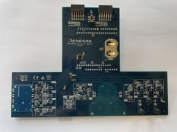
RL78/G23 感应式接近传感扩展板
RL78/G23 感应式接近传感扩展板是一款用于 RL78/G23 微控制器 64 引脚快速原型板 (FPB) 的插接式扩展板,专为感应式传感应用的原型开发而设计。 将这块扩展板安装到 64 引脚 G23 FPB 即可开始评估工作,无需用到其他工具。 通过这个出色的组合,您即刻就能感受到 RL78/G23 在感应式近距离传感应用中的强大能力与适用性。
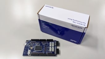
RL78/G23-128p 快速原型开发板
RL78/G23-128p 快速原型开发板采用 RL78/G23 微控制器,是各种原型开发的理想选择。 它通过示例代码支持通过 Wi-Fi DA16600模块的 AWS 云连接、OTA 固件更新、LoRa 和基于 LoRaWAN 的无线通信等功能。 内置的仿真器电路相当于 E2 仿真器 Lite,无需额外工具即可进行编程和调试。 此外,它还具有 Arduino Mega、Pmod™ 和 Grove 接口,可连接所有微控制器引脚,并且具有高可扩展性。 它包括两个触摸按钮,使用 RL78/G23 独有的电容式传感器单元。 瑞萨电子还提供了一个 Arduino 库,支持在 Arduino... 阅读详情
产品选项
| 器件号 | 状态 | 库存 | 预算价格(美元) | Sampleable |
|---|---|---|---|---|
| RTK7RLG230CLG000BJ | Active | 有库存 | 1u | $18.82 | Available |
视频和培训
This video demonstrates how to debug sketches using the RL78 Arduino library on a Windows PC within the Arduino IDE. Through debugging, developers can collect detailed information from their sketches and observe the internal behavior of the library. The tutorial uses the RL78/G23‑64p Fast Prototyping Board to illustrate the process step by step.
新闻和博客
支持


